Designing, Constructing, And Testing A Low – Speed Open
advertisement
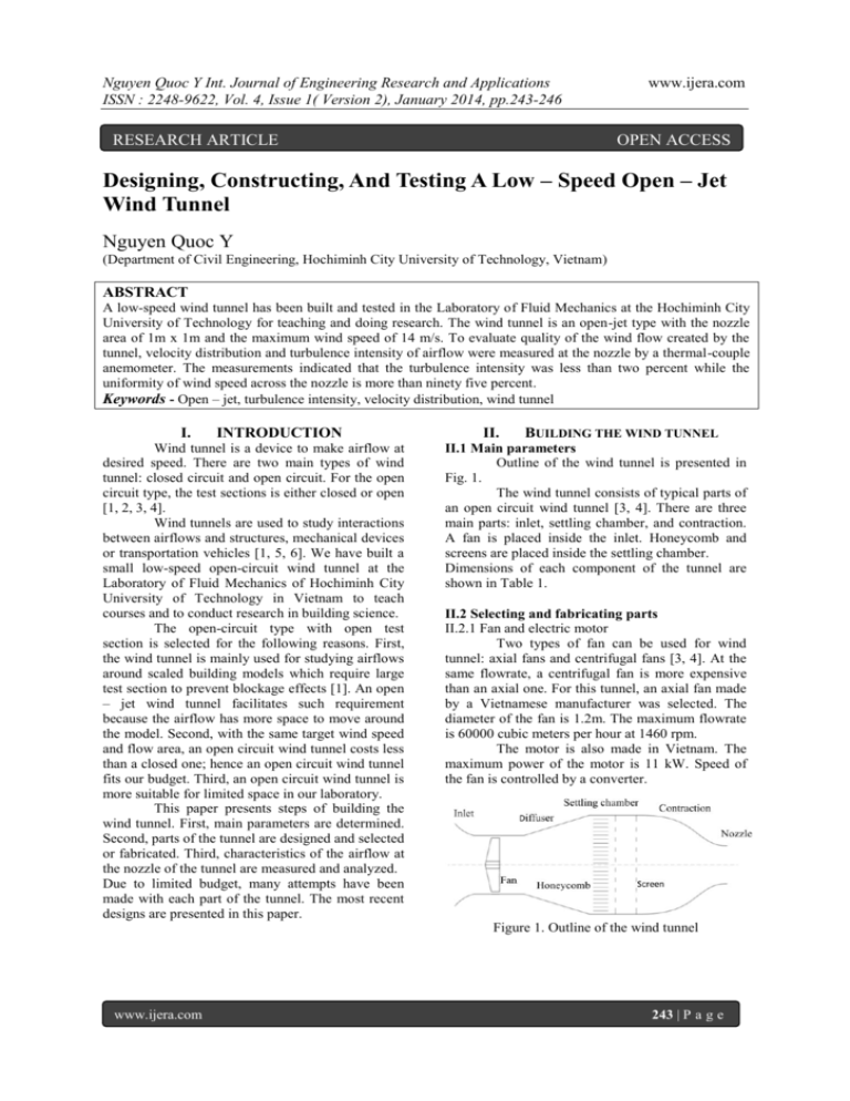
Nguyen Quoc Y Int. Journal of Engineering Research and Applications ISSN : 2248-9622, Vol. 4, Issue 1( Version 2), January 2014, pp.243-246 RESEARCH ARTICLE www.ijera.com OPEN ACCESS Designing, Constructing, And Testing A Low – Speed Open – Jet Wind Tunnel Nguyen Quoc Y (Department of Civil Engineering, Hochiminh City University of Technology, Vietnam) ABSTRACT A low-speed wind tunnel has been built and tested in the Laboratory of Fluid Mechanics at the Hochiminh City University of Technology for teaching and doing research. The wind tunnel is an open-jet type with the nozzle area of 1m x 1m and the maximum wind speed of 14 m/s. To evaluate quality of the wind flow created by the tunnel, velocity distribution and turbulence intensity of airflow were measured at the nozzle by a thermal-couple anemometer. The measurements indicated that the turbulence intensity was less than two percent while the uniformity of wind speed across the nozzle is more than ninety five percent. Keywords - Open – jet, turbulence intensity, velocity distribution, wind tunnel I. INTRODUCTION Wind tunnel is a device to make airflow at desired speed. There are two main types of wind tunnel: closed circuit and open circuit. For the open circuit type, the test sections is either closed or open [1, 2, 3, 4]. Wind tunnels are used to study interactions between airflows and structures, mechanical devices or transportation vehicles [1, 5, 6]. We have built a small low-speed open-circuit wind tunnel at the Laboratory of Fluid Mechanics of Hochiminh City University of Technology in Vietnam to teach courses and to conduct research in building science. The open-circuit type with open test section is selected for the following reasons. First, the wind tunnel is mainly used for studying airflows around scaled building models which require large test section to prevent blockage effects [1]. An open – jet wind tunnel facilitates such requirement because the airflow has more space to move around the model. Second, with the same target wind speed and flow area, an open circuit wind tunnel costs less than a closed one; hence an open circuit wind tunnel fits our budget. Third, an open circuit wind tunnel is more suitable for limited space in our laboratory. This paper presents steps of building the wind tunnel. First, main parameters are determined. Second, parts of the tunnel are designed and selected or fabricated. Third, characteristics of the airflow at the nozzle of the tunnel are measured and analyzed. Due to limited budget, many attempts have been made with each part of the tunnel. The most recent designs are presented in this paper. II. BUILDING THE WIND TUNNEL II.1 Main parameters Outline of the wind tunnel is presented in Fig. 1. The wind tunnel consists of typical parts of an open circuit wind tunnel [3, 4]. There are three main parts: inlet, settling chamber, and contraction. A fan is placed inside the inlet. Honeycomb and screens are placed inside the settling chamber. Dimensions of each component of the tunnel are shown in Table 1. II.2 Selecting and fabricating parts II.2.1 Fan and electric motor Two types of fan can be used for wind tunnel: axial fans and centrifugal fans [3, 4]. At the same flowrate, a centrifugal fan is more expensive than an axial one. For this tunnel, an axial fan made by a Vietnamese manufacturer was selected. The diameter of the fan is 1.2m. The maximum flowrate is 60000 cubic meters per hour at 1460 rpm. The motor is also made in Vietnam. The maximum power of the motor is 11 kW. Speed of the fan is controlled by a converter. Figure 1. Outline of the wind tunnel www.ijera.com 243 | P a g e Nguyen Quoc Y Int. Journal of Engineering Research and Applications ISSN : 2248-9622, Vol. 4, Issue 1( Version 2), January 2014, pp.243-246 Table 1. Dimensions of main parts of the tunnel. Items Dimensions Nozzle sectional area 1m x 1m Contraction length 1.5m Settling chamber cross section 1.8m x 1.8m area Settling chamber length 1.59m Diffuser length 1.0m Inlet diameter 1.28m Inlet length 0.7m Total length of the tunnel 4.79m www.ijera.com Two low-cost methods were tried for the honeycomb: using cooling pad and using straws with similar cell diameter of about 10mm, as shown in Fig. 3. Measurements conducted after installing each method showed that the maximum velocity at the nozzle for the cooling pad was about 10 m/s while that for the straws was about 14 m/s. Turbulence intensities of the two methods were almost identical. Consequently, the straws were selected. II.2.2 Inlet section The inlet is a cylinder with a diameter of 1.28m which is slightly larger than the diameter of the fan. The mouth of the inlet section was rounded. A wood frame supports the inlet section. Fig. 2 shows the fabricated inlet section. Figure 3. Two methods for the honeycomb: cooling pad (left) and straws (right). Figure 2. Fabricated inlet section II.2.4.2 Screens Screens help to increase uniformity of the airflow as passing through a screen, faster flows have more pressure drop than slower ones. Frontal area of the screen should not be more than 40% the cross sectional area of the settling chamber to ensure flow stability. For our tunnel, two screens with cell size of 10 mm x 10mm made by steel wires of 1mm diameter were selected and placed behind the honeycomb. The frontal area of these screens are about 20% the cross sectional area of the settling chamber. II.2.3 Diffuser The diffuser connects the inlet section and the settling chamber. It is required that there is no flow separation inside this section. The area ratio between the inlet (i.e. of the inlet section) and the outlet (i.e. of the settling chamber) of the diffuser is 2. It is suggested that the maximum diffuser angle suitable for that ratio to prevent flow separations is 20o [4]. The diffuser angle of our design is 14 o. II.2.4 Settling chamber The main purpose of the settling chamber is to make the flow become straight, less turbulent and more uniform. Its important components are honeycomb and screens. II.2.4.1 Honeycomb Honeycomb helps to cease tangential velocity of the airflow caused by the axial fan. It also reduces turbulence level of the airflow. According to Mehta and Bradshaw [4], there should be 150 cells per chamber hydraulic diameter Dh. The cell length should be about 6 – 8 times its diameter. For the dimensions of our settling chamber, diameter of each cell should be less than 12mm. www.ijera.com II.2.4.3 Length of the settling chamber Spacing between the screens should be enough so that flow pressure has fully recovered from the perturbation as the flow passes through the screen before reaching the next one. An optimal spacing of 0.2Dh was suggested [4]. In addition, the spacing between the last screen and the contraction should be also 0.2Dh. With two screens and Dh of 1.8m, the total length of the settling chamber is 1.59m. II.2.5 Contraction Contraction is the most important component of a wind tunnel because it strongly affects quality of the airflow in the test section [2, 4]. As the flow area reduces, the flow speeds up through the contraction. Three main parameters of a contraction are contraction ratio (ratio between area at inlet and outlet), wall shape, and contraction length. They are computed carefully so that there is no flow separation inside the contraction. Thickness of the boundary layer at the outlet is minimized. On the other hand, the contraction length should be as short as possible for cost and space savings. 244 | P a g e Nguyen Quoc Y Int. Journal of Engineering Research and Applications ISSN : 2248-9622, Vol. 4, Issue 1( Version 2), January 2014, pp.243-246 Bell and Mehta [2] proposed optimal wall shape of polynomial functions. The fifth order functions was selected for our wind tunnel: y(x) = Hi – (Hi – He) [6(x')5 – 15 (x')4 +10(x')3] (1) Where: - x and y are horizontal and vertical coordinates, respectively, - Hi is half of the inlet height of the contraction (0.9m), - He is half of the outlet height of the contraction (0.5m), - x'=x/L; L is the length of the contraction. Contraction ratio of our wind tunnel is 3.24. For this ratio, the length L should be in the range of [0.89 – 1.64] Hi. With Hi equals 0.9m, the length L of 1.5m yields the ratio L/Hi of 1.67. To make the contraction, guide beams were fabricated by CNC machines to match the selected profile (1). They were joined together to form the frame of the contraction. Steel sheets of 1mm were then welded on the frame to make wall of the contraction. Figure 5 shows the CAD model and fabricated contraction. www.ijera.com - Velocity at the center of the nozzle at different fan speeds. - Velocity distributions across the nozzle along vertical and horizontal directions. Fig. 7 shows velocities at the center of the nozzle at different fan speeds. As the fan speed increases, both mean velocity and velocity fluctuation increase as well. Figure 7. Velocity measured at the center of the nozzle at different fan speeds. Averaged velocity Vi at a fan speed is obtained by the following equation [5]: (2) Where N=600 is the number of samples; vj is the instantaneous velocity of the sample j. Turbulence intensity for the mean velocity Vi is [5]: Figure 5. CAD model (left) and fabricated contraction (right). (3) The finished wind tunnel is shown in Fig. 6. Figure 6. The finished wind tunnel: viewed from the nozzle (left) and from the inlet section (right). II.3 Limitations of the design We have not considered pressure drops through parts of the wind tunnel. The main reason is that the manufacturer did not provide any information about the head of the fan. Therefore, the fan selection was based only on the target flowrate and velocity at the nozzle. III. TESTING THE WIND TUNNEL Velocity at the nozzle was measured with a hotwire anemometer. The resolution of the device was 1cm/s. Two measurements were conducted: www.ijera.com Figure 8. Averaged velocity and turbulence intensity at different fan speeds. The mean velocities and turbulence intensities for the data in Fig. 7 is presented in Fig. 8. The averaged velocity increases linearly with the fan speed. At the fan speed of 1300 rpm, the averaged velocity is about 13m/s. It is expected that the maximum velocity reach 14.6m/s at the maximum fan speed of 1460 rpm. 245 | P a g e Nguyen Quoc Y Int. Journal of Engineering Research and Applications ISSN : 2248-9622, Vol. 4, Issue 1( Version 2), January 2014, pp.243-246 For the averaged velocity above 2m/s, the turbulence intensity is always below 2%. This value is similar to some other wind tunnels [6]. It is also observed that the turbulence intensity is lower at higher velocity. Fig. 9 shows velocity distributions along horizontal and vertical directions through the center of the nozzle. [2] [3] [4] [5] [6] www.ijera.com Bell J. H. and Mehta R. D., Contraction design for small low-speed wind tunnels, Report, Stanford University, 1998. Boudreau III H.S., Design, construction, and testing of an open atmospheric boundary layer wind tunnel, Bachelor Thesis, University of Florida, 2009. Mehta R.D. and Bradshaw P., Design rules for small low speed wind tunnels, The aeronautical journal of the aeronautical society, 1979, 443-449. Pope S.B., Turbulent flows (Cambridge University Press 2002). Ghorbanian K, Soltani M.R., Manshadi M.D., Experimental investigation on turbulence intensity reduction in subsonic wind tunnels, Aerospace science and technology, 15, 2011, 137 – 147. Figure 9. Velocity distributions along vertical and horizontal directions at the nozzle. The velocity is slightly higher towards the rear of the nozzle. This may be because the contraction ratio of our tunnel is just 3.24; hence the airflow near the wall of the contraction speeds up more than the one near the center. However, the standard deviations of the velocity distributions are below 4.5%. IV. CONCLUSION We have built a low – speed open – jet wind tunnel. Although the wind tunnel is simple and low-cost, measurements of air velocity at the nozzle show that the velocity distribution and turbulence intensity are acceptable for teaching and doing basic researches in building science. The design of this wind tunnel also offers us valuable experience to build larger wind tunnel in the future. ACKNOWLEDGEMENTS The author appreciates supports from Hochiminh City University to build the wind tunnel. Valuable helps from colleagues at the Laboratory of Fluid Mechanics are also appreciated. REFERENCES [1] Aurelius L.J. and Rofail A.W., Performance of Windtech’s slatted roof blockage tolerant boundary layer wind tunnel in 3D flow, 9th AWES Workshop, Townsville, 12-13 July, 2001. www.ijera.com 246 | P a g e
