Physics 241 Lab: Motors

Physics 241 Lab: Motors
http://bohr.physics.arizona.edu/~leone/ua/ua_spring_2010/phys241lab.html
Name:____________________________
Section 1:
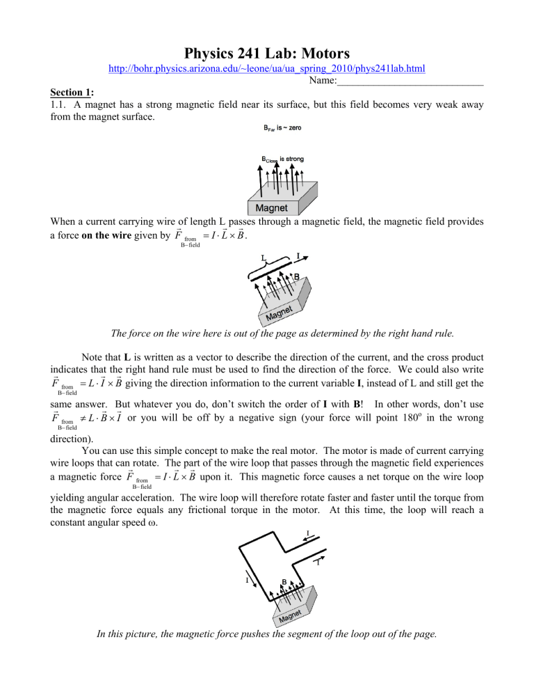
1.1. A magnet has a strong magnetic field near its surface, but this field becomes very weak away from the magnet surface.
When a current carrying wire of length L passes through a magnetic field, the magnetic field provides a force on the wire given by F
B from
field
I
L
B .
The force on the wire here is out of the page as determined by the right hand rule.
Note that L is written as a vector to describe the direction of the current, and the cross product indicates that the right hand rule must be used to find the direction of the force. We could also write
F
B from
field
L
I
B giving the direction information to the current variable I , instead of L and still get the same answer. But whatever you do, don’t switch the order of
F
from
B
field
L
direction).
B
I
I with B ! In other words, don’t use
or you will be off by a negative sign (your force will point 180 o
in the wrong
You can use this simple concept to make the real motor. The motor is made of current carrying wire loops that can rotate. The part of the wire loop that passes through the magnetic field experiences a magnetic force F
from
B
field
I
L
B upon it. This magnetic force causes a net torque on the wire loop yielding angular acceleration. The wire loop will therefore rotate faster and faster until the torque from the magnetic force equals any frictional torque in the motor. At this time, the loop will reach a constant angular speed
.
In this picture, the magnetic force pushes the segment of the loop out of the page.
How could you make a more powerful motor using an extra amount of wire? Your answer:
How could you make a more powerful motor using an extra magnet? Provide a small sketch with your answer. Your answer and sketch:
1.2. The only difficulty in making a motor is to ensure that the current always travels in the same direction as it passes through the magnetic field no matter how the loop itself is oriented. Examine the following picture to better understand what this difficulty is if the current supplied to the wire loop is always the same for each lead of the wire loop:
In this before-and-after picture, you can see that when the wire loop rotates 180 o
the force will now push the loop in the opposite direction because the direction of the current through the magnetic field will be reversed. Unless you want to make a fancy electronic rocking chair, this is not good motor design.
Instead, you will need to design your motor so that the current always flows in the same direction for the part of the wire loop inside the magnetic field as is shown in the next picture:
In this motor set-up (previous picture), when the wire loop rotates 180 o
, the manner in which current is supplied to the loop is changed in order to get the current to flow in the same direction for the part of the loop experiencing the magnetic force.
1.3. The figure below shows three possible arrangements for a current carrying wire to pass between two magnets. For each case, use the Lorentz force equation to compare the resulting force on the segment of current carrying wire (relative magnitude and direction). You are not provided a numerical value of B so you need to give a qualitative description of the strength of the force. A picture of an actual current carrying wire in a magnetic field is also provided to motivate your solution.
Your answer:
1.4. A is a motor in reverse. Instead of taking electrical power from a current and turning it into mechanical energy (the rotation of the motor), a generator takes mechanical energy and turns it into electrical power by providing a current. Imagine taking a motor and disconnecting it from its DC power supply and connecting it to a light bulb. If you motor had a hand-crank, then you could provide the mechanical energy to create the current in the light bulb. In today’s lab, what would you see on the oscilloscope screen if you connected your motor to one of the oscilloscope channels and turned the motor with your fingers? Your quick sketch:
1.5. The following four sections provide information that is especially useful in completing the lab.
1.5.1. Power & Efficiency
At some time, the rotation rate
reaches an equilibrium where the opposing torques balance the torque caused by the magnetic force, T
from
B
field
T opposing
. These opposing torques come from friction and any load you place on the motor (work you make it do). In this experiment, it will be difficult to directly analyze the magnetic force being applied to the motor so that the force-torque perspective will not be useful. Therefore, it is better to examine the energy perspective of the motor.
Specifically, P input
P output
P friction
where the input power can easily be measured in the lab as power power
P input power
I through
V across motor motor
and the output power is equal to the work energy that the motor performs per second.
However, the motor will not always be able to make contact through the wire brushes so that current does not flow to the motor at all times. If the motor is only in contact with the source for 30% of the time, then P input
0.3
I through
V across
. The oscilloscope in the lab is very useful in determining power motor motor what percentage of the time current is flowing through the motor.
In order to measure the current through the motor, a rather imprecise value is obtained from the power supply readout. A much better value for the current may be obtained by placing the motor in series with a 1
resistor and using the oscilloscope to find the current through the resistor (and therefore the motor).
The efficiency of the motor is given by
efficiency
P output power
P input power
. If the motor is made to lift objects vertically, then the output power can be found via the force of gravity:
E output
mgh so that P output power
E output
t
mg
h
t
.
1.5.2. Speed of Rotation
The rotational speed of a motor is typically measured in revolutions per minute (RPM). You will need to use the oscilloscope to find the time of one full oscillation (the period), turn this into frequency, and finally into RPM. Use simple factor labeling with f cycles
60
f cycles seconds
60 seconds
1 minute
minute
60
f revolutions minute
60f RPMs .
1.5.3. Warning about Motor Destruction
The wire insulation melts at approximately 5 amps of intermittent current. Once the insulation melts, all the loops are shorted out so that you only have one loop to drive the motor (not good).
Do not use too large of an input power.
Do not let the motor get stuck with current flowing through its nearly resistanceless wires.
(Otherwise the wires are the only resistor in the circuit and become very hot.)
1.5.4. Observing the Motor Parameters
The easiest way to observe the behavior of the motor is with a middle ground measurement between a 1
resistor and the motor in series. This will provide the following graph on the oscilloscope screen, though it may take some effort to find the correct time scale. The percent of time that the motor is on is simply (t
1
+t
2
) / T. Using the run/stop button to collect data from the oscilloscope is useful for this because the triggering will be very sensitive and the will continuously lose the signal.
Later in the lab you will need to measure these two components simultaneously in order to calculate the RPMs and the power. Since
P motor,on
I motor,on
I resistor,on
V motor,on
V motor,on
fraction of time on
fraction of time on
V resistor,on
V motor,on
fraction of time on
R you can obtain the power used by the motor (friction) using only the pictured measurements.
Section 2. Construct your motor:
2.1. Begin with your card. Write your name on the card by the box containing the word “magnet”.
2.2. Cut along the solid lines and fold along the dotted lines. Taking your time to make things nice in the motor construction will ensure your motor runs well and is easily fixed if it breaks down.
2.3. Carefully use a sharp poker to poke out the marked black dots. Wiggle the two axial dots so that the motor axis will turn easily (with low friction). Never poke through the paper with your finger on the other side. Always lay the paper flat on the table surface and poke so that the poker strikes the table when exiting the paper.
2.4. Use masking tape or clear tape to tape up your motor-enclosure box and armature box.
2.5. At this point, examine what a finished motor should look like.
2.6. Tape your magnet into your box, and add tape to the axle rod. The tape in the axle rod serves the dual purpose of insulating wires from the metal rod as well as keeping the rod positioned correctly in the motor-enclosure box: so the armature box stays above the magnet. Pay careful attention to locate the insulating tape on the correct location of the rod by repeatedly placing the rod into the motorenclosure box and spinning it with your fingers.
2.7. Add some tape as neatly as possible to affix the axle rod to the armature box.
2.8. Take ~2 metes of wire and wrap the armature box. Both ends of the wire should protrude from the winding box along the axle insulation. You will eventually bare the two ends and tape them down to the axle, but leave them free until you learn how to bare the wires. Notice that the two ends of the winding protrude to the left of the armature box and are taped down flat against the axle and in the place of the armature box . If the leads are not in the plane of the armature box, the coil will receive current when the coil is 90 o
rotated away from the magnet (not good).
2.9. Wherever good electrical contact is desired, the colored insulation must be burned and sanded off that part of the wire so that clean, bright copper can be seen. To bare the wire you must burn off the insulation along the part of the wire you wish to bare. Burn the insulation thoroughly; it will appear blackened. Then use sandpaper to clean the charred wire insulation and leave a nice bright, bared length of copper wire.
2.10. Place the axle into the motor-enclosure box. You may eventually need to add tape to other parts of the axle in order to keep the axel from shifting around too much in the motor-enclosure box during operation.
2.11. Finally you must insert two bared wires to act as brushes for your motor. These “power lines” are the most difficult part of the motor to get correct. The axle leads must make precise contact with these power lines as the motor turns. Motors that work best tend to have very straight brushes that lie tightly against the axle. Note that the location of the power lines (the punched holes in the sides of the motor-enclosure box) may need to be changed depending on the final position of your axle leads.
( See the next page for power line hints.
)
Other power line configurations have shown improvement over the original design. One idea is to double up the power lines so that they make better contact and are more durable:
Another idea is to change the location of the power lines so that they “hug” the axle more than in the original positioning:
2.12. Always start with low voltage (~2 Volts) when connecting your motor to the DC power supply.
Then start the motor by spinning it with your fingers. You should be able to feel with your fingers which way the motor is being pushed to rotate. This will tell you which way to spin it. You may have to keep increasing the supply voltage to keep your motor spinning. Never let your motor stay connected to the source with current running through it when it is not spinning because the insulation will rapidly melt away. (You may hear your TA shouting in the room, “Unhook it! Unhook it!”)
Section 3: You must demonstrate a working motor (each person in your group must build their own motor).
YOUR MOTOR WORKS (TA Signature): ___________________________________________
Section 4: (Open-ended question / creative lab design)
Imagine you wish to sell your motor on Ebay. You will need to describe as many of your motor’s features in addition to your intense emotional attachment to your motor. Design a way to calculate the minimum source voltage required to operate your motor V source,min
, the RPMs at this voltage RMS min
, and the power loss due to frictional torque P motor,on
. Note that you cannot obtain an accurate measure of voltage or current with the built-in source meters so must use the oscilloscope to find these values. Also you should report the maximum safe source voltage V source,max
and corresponding RPMs RPM max your motor can operate safely at.
At the following prompts, design an experiment to find the parameters needed to sell your motor on Ebay. Then implement your experiment and record your observations. You may “cheat” by talking to other groups for ideas, but not “cheat” by already knowing the answer or looking it up.
Your planned experiment, sketch of actual implementation and any theoretical calculations:
Your observations:
Your explanations & conclusion:
Report Guidelines: Write a separate section using the labels and instructions provided below. You may add diagrams and equations by hand to your final printout. However, images, text or equations plagiarized from the internet are not allowed!
Title – A catchy title worth zero points so make it fun.
Goals – Do not write this section. [~0-point]
Concepts & Equations – [4-points] Be sure to write a separate paragraph to explain each of the following concepts.
Explain how a motor works. Be sure to describe the physical laws that enable a motor to work.
Explain how a generator works.
Procedure & Results – Do not write this section. [~0-points]
Conclusion – Write at least three paragraphs where you analyze and interpret the results you observed or measured based upon your previous discussion of concepts and equations. It is all right to sound repetitive since it is important to get your scientific points across to your reader.
Write a separate paragraph analyzing and interpreting your results from your open-ended experiment. Do NOT write personal statements or feeling about the learning process (keep it scientific). [~1-points]
Graphs – None. [~0-points]
Extra – Make your motor work for a non-classmate and have them sign an affidavit confirming that they saw your motor work. You do not need to have the affidavit witnessed by a notary.
[~5-points]
Worksheet – thoroughly completed in class and signed by your TA. [~15-points]


