AP Physics Homework Solutions Unit 9: Electric Circuits Homework
advertisement
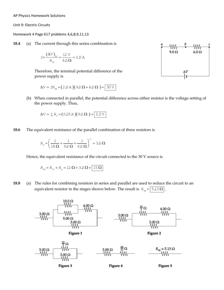
AP Physics Homework Solutions Unit 9: Electric Circuits Homework 4 Page 617 problems 4,6,8,9,11,13 18.4 (a) The current through this series combination is I V bc Rbc 12 V 2.0 A 6.0 Therefore, the terminal potential difference of the power supply is V IReq 2.0 A 9.0 6.0 30 V (b) When connected in parallel, the potential difference across either resistor is the voltage setting of the power supply. Thus, V I9 R9 0.25 A 9.0 2.3 V 18.6 The equivalent resistance of the parallel combination of three resistors is 1 1 1 1 Rp 3.0 18 9.0 6.0 Hence, the equivalent resistance of the circuit connected to the 30 V source is Req R12 R p 12 3.0 15 18.8 (a) The rules for combining resistors in series and parallel are used to reduce the circuit to an equivalent resistor in the stages shown below. The result is Req 5.13 . (b) From P V Req , the emf of the power source is 2 V PReq 18.9 4.00 W 5.13 4.53 V Turn the circuit given in Figure P18.9 90° counterclockwise to observe that it is equivalent to that shown in Figure 1 below. This reduces, in stages, as shown in the following figures. From Figure 4, I V 25.0 V 1.93 A R 12.9 (b) From Figure 3, V ba IRba 1.93 A 2.94 5.68 V (a) From Figures 1 and 2, the current through the 20.0 resistor is I20 V ba 5.68 V Rbca 25.0 0.227 A 18.11 The equivalent resistance is Req R R p , where R p is the total resistance of the three parallel branches; 30 R 5.0 1 1 1 1 1 Rp R 35 120 40 R 5.0 30 R 5.0 1 Thus, 75 R 1 30 R 5.0 R 2 65 R 150 2 R 35 R 35 which reduces to R 2 10 R 2475 2 0 or R 55 R 45 0 . Only the positive solution is physically acceptable, so R 55 18.13 The resistors in the circuit can be combined in the stages shown below to yield an equivalent resistance of R ad 63 11 . From Figure 5, I V ad R ad Then, from Figure 4, 18 V 3.14 A 63 11 V bd IRbd 3.14 A 30 11 8.57 V Now, look at Figure 2 and observe that I2 so V bd 3.0 2.0 8.57 V 1.71 A 5.0 71 A 3.0 5.14 V V be IR 2 be 1. Finally, from Figure 1, I12 V be 5.14 V R12 12 0.43 A
