problem 25
advertisement
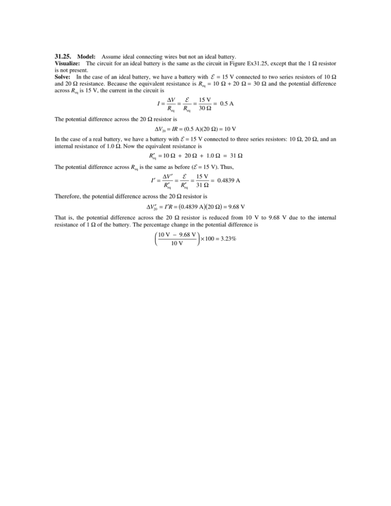
31.25. Model: Assume ideal connecting wires but not an ideal battery. Visualize: The circuit for an ideal battery is the same as the circuit in Figure Ex31.25, except that the 1 Ω resistor is not present. Solve: In the case of an ideal battery, we have a battery with E = 15 V connected to two series resistors of 10 Ω and 20 Ω resistance. Because the equivalent resistance is Req = 10 Ω + 20 Ω = 30 Ω and the potential difference across Req is 15 V, the current in the circuit is I= ∆V E 15 V = = = 0.5 A Req Req 30 Ω The potential difference across the 20 Ω resistor is ∆V20 = IR = (0.5 A)(20 Ω) = 10 V In the case of a real battery, we have a battery with E = 15 V connected to three series resistors: 10 Ω, 20 Ω, and an internal resistance of 1.0 Ω. Now the equivalent resistance is Req′ = 10 Ω + 20 Ω + 1.0 Ω = 31 Ω The potential difference across Req is the same as before (E = 15 V). Thus, I′ = ∆V ′ E 15 V = = = 0.4839 A Req′ Req′ 31 Ω Therefore, the potential difference across the 20 Ω resistor is ∆V20′ = I ′R = (0.4839 A )(20 Ω) = 9.68 V That is, the potential difference across the 20 Ω resistor is reduced from 10 V to 9.68 V due to the internal resistance of 1 Ω of the battery. The percentage change in the potential difference is 10 V − 9.68 V × 100 = 3.23% 10 V
