Resonance phenomenon in a forced damped
advertisement
1
Resonance phenomenon in a forced damped oscillator
Zakir Z. Thaver
Physics Department, The College of Wooster, Wooster, Ohio 44691
April 30, 1998
The ratio of the viscosity of water to air was measured in this experiment
using a Driven Harmonic Motion Analyzer. The amplitude of an
oscillating 50g mass was measured in air and in water for various driving
frequencies. The resonant amplitudes for the mass in air and water were
found to be 156 ± 2 mm and 76 ± 2 mm respectively. An estimate for
the viscosity of air was 0.12 ± 0.006 Ns/m and that of water was 0.24 ±
0.002 Ns/m. The resulting ratio of the viscosities was found to be
2.0± 0.1. The published value for the same is 55.56.
INTRODUCTION:
mx˙˙ + bx˙ + kx = Fo cosωt
A child using a swing realizes that if the
pushes are properly timed, the swing can move
with a very large amplitude. The driving force, in
this case the agent pushing the swing, exactly
replenishes the energy that the system loses if its
frequency equals the natural frequency of the
system. This phenomenon is called resonance.
More formally, it is the maximum response of a
system when its natural frequency becomes equal
to the forcing frequency.
An example of resonance occurred in the
Tacoma Narrows Bridge in Washington State in
1940. The wind blowing through the Tacoma
Narrows broke up into vortices which provided
puffs of wind that shook the bridge at a frequency
that matched one of its natural vibrational
frequencies.
Resonance shows up in many
physical systems and is hence of great
importance.
The fact that resonance occurs in the
Driven Harmonic Motion Analyzer used in this
experiment was made use of, by modeling, to
calculate the viscosities of different media.
Dividing both sides of equation (1) by the mass,
m yields
THEORY:
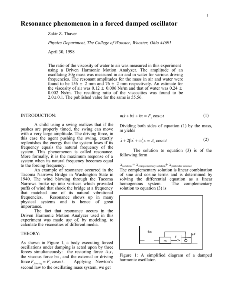
As shown in Figure 1, a body executing forced
oscillations under damping is acted upon by three
forces simultaneously: the restoring force -k x ,
the viscous force b x˙ , and the external or driving
force F forcing = F o cosωt .
Applying Newton’s
second law to the oscillating mass system, we get
(1)
x˙˙ + 2β x˙ + ω 2o x = Ao cosωt
(2)
The solution to equation (3) is of the
following form
xsolution = x complementary solution+ x particular solution
The complementary solution is linear combination
of sine and cosine terms and is determined by
solving the differential equation as a linear
homogenous system.
The complementary
solution to equation (3) is
-kx
F
m
b x˙
>
Figure 1: A simplified diagram of a damped
harmonic oscillator.
2
x c (t ) = e − βt [ A1 exp( β 2 − ωo2 )
+ A2 exp(− β 2 − ω o2 )]
A
= β Dmax
2ω o
Combining eqn. (11) with eqn. (9) we get
and the particular solution for equation (2) is
D=
(3)
(4)
x p (t) = D cos(ωt − δ)
where D is the amplitude of the particular
solution, and δ is the phase shift between the
driving force and the system response. The
complementary solution given by the equation (3),
is a short-lived transient: the amplitudes it
describes die out due to the exponential decay
term. After waiting long enough, only the
particular solution, given by equation (4) is
worthy of consideration. Substituting equation (4)
into equation (3) yields the relation
{A − D[(ω 2o − ω 2 )cos δ + 2ωβ sin δ]}cosωt
(5)
−{D[(ω o2 − ω 2 )sin δ + 2ωβ cosδ]}sin ωt = 0
Solving for D gives the equation
A
(6)
(ω − ω ) + 4ω 2 β 2
The resonance frequency can be determined by
maximizing the amplitude function with respect to
frequency. This is achieved by taking the partial
derivative of equation (6) and equating it to zero.
The resulting relationship is
D=
2
o
2 2
(7)
ω R = ω o2 − 2β 2
where ω R is the angular frequency at resonance.
In the case of weak damping, it can be assumed
that β << ω o and ω R ≅ ω o , Therefore let
∆ω = (ω o − ω) so that
(8)
(ω o2 − ω 2 ) = (ω o − ω )(ω o + ω ) ≈ −2ω o ∆ω
which when substituted into equation (6) gives
D=
A
A
(9)
=
2
2
2 2
2
2
4ω (∆ω) + 4ω o β
2ωo (∆ω ) + β
2
o
At maximum amplitude of the particular solution,
∆ω = 0. If this amplitude is called Dmax then
Dmax (ω o = ω ) =
or
A
2ω oβ
(10)
βDmax
(ω o − ω )2 + β 2
(11)
(12)
which is a Lorentzian line shape.
EXPERIMENTAL SETUP:
The sole apparatus for this experiment was
a Pasco Scientific Driven Harmonic Motion
Analyzer, Model 9210. The Motion Analyzer unit
was leveled using the adjustable screws under its
base. A bubble leveling device was used as a
guide. It was ensured that there was no friction
between the mass bar/displacement scale and the
upper mass guide, and also the damping rod and
the lower mass guide. This was achieved by
slightly rotating the lower and upper mass guides
so as to prevent them from rubbing against the
displacement scale and damping rod.
EXPERIMENTAL PROCEDURE:
The frequency of the driving force was
increased gradually until the amplitude of the
mass was noticeable. The smallest amplitude
observed was 16mm at a driving frequency of
1.60Hz. From here, the frequency was increased
by 0.02Hz and the corresponding amplitudes were
recorded. Each time the frequency was increased
in this manner, the system was allowed sufficient
time (typically 30 s to 1 minute) to stabilize. A
digital display on the motion analyzer could be set
to display either the driving frequency, or the
amplitude, by changing the position of a Function
knob.
The Motion Analyzer measures the driving
frequency by an optical sensor that counts bars on
a rotating disc. As a result, it would not rotate the
same number of bars past the sensor every time.
The reading on the digital display, indicated for
example 1.64Hz on one reading and 1.65Hz on
the next. The fluctuating frequency values made it
seem difficult to take an accurate measurement of
frequency, but the digital display was watched for
a few seconds and a mental average was taken.
Since the driving frequency knob rotates smoothly
and without clicking at specific intervals, it had to
be rotated extremely slowly to obtain a difference
of 0.02Hz for successive readings.
The amplitude of the mass is measured
similarly by an optical sensor counting bars on the
Mass bar and displacement scale. Fluctuations in
the amplitude were compensated for by taking a
3
mental average of the different (but nearby)
values of amplitude.
In the first data set, the mass was allowed
to oscillate freely in air. For the second data set ,
the damping rod was placed into a cylinder
containing water. It was made sure that the mass
was not rubbing against the sides of the
cylindrical vessel while oscillating.
EXPERIMENTAL RESULTS:
While oscillating in air, the amplitude of
the mass increased dramatically at resonance. It
jumped from 101± 2mm at a frequency of 1.75 ±
0.01Hz to 162 ± 2mm at a resonant frequency of
1.76 ± 0.01 Hz . In water the resonant amplitude
was significantly smaller, and the resonant
frequency was slightly shifted. The amplitude of
the mass in water, at resonance was found to be
81± 2mm at a frequency of 1.78 ± 0.01Hz. The
increase in amplitude at resonance was not as
dramatic. The amplitude in water just before
resonance was 74 ± 2mm at a frequency of
1.76± 0.01Hz.
The amplitude of the oscillating mass
squared was plotted against the angular frequency
for air and water using Igor Pro version 3.01.
Figure 2(a) show the plot for the mass oscillating
in water. Figure 2(b) shows the same for air.
The graphs obtained are approximately
symmetrical about their peaks. This demonstrates
that only at a particular frequency, the response of
the system is maximum, at progressively higher
or lower frequencies the response decreases. The
Lorentzian best fit curve fits the data very well. At
low amplitudes, the co-ordinates are smeared
close together, however at amplitudes close to the
resonant amplitude, the systems response
increased sharply for a slight increase in
frequency, and hence data co-ordinates are farther
apart. In Figure 2(b), the amplitudes of oscillation
in air and water are almost the same till an angular
frequency of 10.8 rad/s, close to the resonant
angular frequency there is a substantial difference
in amplitude. The amplitudes tend to become
equal again at an angular frequency of 12.0 rad/s.
The resonant peak for the oscillations in water is
slightly shifted to the left of the resonant peak for
oscillations in air.
A Lorentzian curve was used to fit the coordinates in Figure 2 in order to model the data
obtained from the experiment. The curve has the
following general form
y = ko +
k1
(x − k2 )2 + k3
(13)
With ko made equal to zero, the above equation
matches the form of equation (14) squared. Hence
2
2
we can identify y=D2 , x = ω , k1 = β D max ,
k1 = β 2 D 2
max
and
k3 = β 2 .
A graph of the amplitude squared (y-axis)
was plotted against the angular frequency (x-axis)
using Igor Pro. (version 3.01). Igor also generated
the values of y, and k1 , k2 and k3 with their
respective uncertainty errors.
The ratio of viscosities is approximately
equal to the ratio of damping constants,
(14)
ηwater β water
≈
η air
β air
The ratio of the viscosity of water to that of air
was found by substituting the values of β for air
and water (generator by Igor Pro version 3.01) in
equation (14).
Igor Pro uses a least squares method in
order to formulate a curve to fit the data. It also
reports the values of the co-efficients in the
Lorentzian function used and their associated
error. Table 1 shows these results for air and
water.
6000
(a)
5000
water]
4000
2
(mm
2
3000
LITUDE
2000
1000
10.5
11.0
11.5
ANGULAR FREQUENCY (rad/s)
3
30x10
)
(b)
25
2
(mm
20
2
PLITUDE
15
10
5
10.2
10.4
10.6
10.8
11.0
11.2
11.4
11.6
11.8
ANGULAR FREQUENCY
Figure 2: Amplitude squared versus angular
frequency for (a) water , and (b) water and air
compared. Note the shift in the resonant
frequency.
4
Table 1: Parameter values and
errors in air and water.
Parameter
AIR
0
ko = 0
2
2
k1 = β Dmax 457± 34
11.119± 0.002
k2 = ωo
0.0141± 0.0014
k3 = β 2
Table 2: Parameter values of
associated errors.
Parameter AIR
β
rad/s 0.12± 0.006
5
2
Dmax mm2 (3.24± 0.41)x10
ω o rad/s 11.119± 0.002
their associated
WATER
0
340± 25
10.99± 0.01
0.0558± 0.0051
interest and their
WATER
0.240± 0.002
(6.09± 0.71)x103
10.99± 0.01
From equation (14),we know that
ηwater β water
≈
= 0.24/0.12 = 2.0± 0.05
η air
β air
The published values for η water is 1.0 x 10⁻³
(Ns/m2 ) and for η air is 1.8 x 10⁻⁵ . 1
CONCLUSION:
The value of the ratio of the viscosities of
water to air is extremely far off from the
published value. This could be a result of the
following: The mass was “X” shaped instead of
being a circular disc, and the damping rod was
extremely thin, due to which the oscillating
system did not experience as much resistance due
to viscosity as an object otherwise would. The
Lorentzian curve fit the data co-ordinates
extremely well suggesting the theory used to
model the experimental results was appropriate.
Also the resonant peaks in water and air were
significantly different as predicted by theory.
Owing to these reasons it can be concluded that
resistance due to viscosity was cut down due to
the nature of the construction of the mass. The
experiment could be extended to investigate the
effect of increased cross sectional area for
constant mass, on the ratio of the viscosities of air
and water.
1
Resnick, Robert, Halliday, David and Krane,
Kenneth, Physics, 4th Edition, Volume 1. John
Wiley and Sons, (1994).
