Gradall XL 3200 V Crawler Excavator Specifications
advertisement
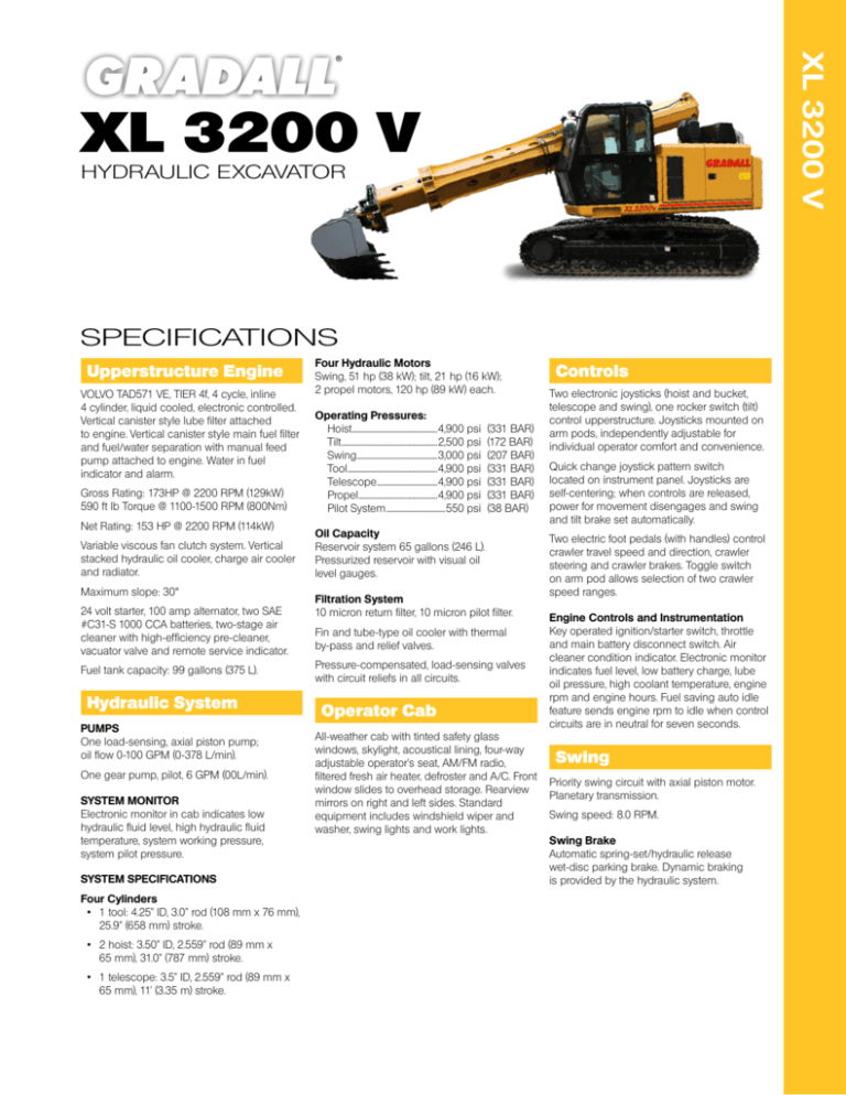
XL 3200 V XL 3200 V HYDRAULIC EXCAVATOR SPECIFICATIONS Upperstructure Engine VOLVO TAD571 VE, TIER 4f, 4 cycle, inline 4 cylinder, liquid cooled, electronic controlled. Vertical canister style lube filter attached to engine. Vertical canister style main fuel filter and fuel/water separation with manual feed pump attached to engine. Water in fuel indicator and alarm. Gross Rating: 173HP @ 2200 RPM (129kW) 590 ft lb Torque @ 1100-1500 RPM (800Nm) Net Rating: 153 HP @ 2200 RPM (114kW) Variable viscous fan clutch system. Vertical stacked hydraulic oil cooler, charge air cooler and radiator. Maximum slope: 30° 24 volt starter, 100 amp alternator, two SAE #C31-S 1000 CCA batteries, two-stage air cleaner with high-efficiency pre-cleaner, vacuator valve and remote service indicator. Fuel tank capacity: 99 gallons (375 L). Hydraulic System PUMPS One load-sensing, axial piston pump; oil flow 0-100 GPM (0-378 L/min). One gear pump, pilot, 6 GPM (00L/min). SYSTEM MONITOR Electronic monitor in cab indicates low hydraulic fluid level, high hydraulic fluid temperature, system working pressure, system pilot pressure. SYSTEM SPECIFICATIONS Four Cylinders • 1 tool: 4.25” ID, 3.0” rod (108 mm x 76 mm), 25.9” (658 mm) stroke. • 2 hoist: 3.50” ID, 2.559” rod (89 mm x 65 mm), 31.0” (787 mm) stroke. • 1 telescope: 3.5” ID, 2.559” rod (89 mm x 65 mm), 11’ (3.35 m) stroke. Four Hydraulic Motors Swing, 51 hp (38 kW); tilt, 21 hp (16 kW); 2 propel motors, 120 hp (89 kW) each. Operating Pressures: Hoist........................................................4,900 psi (331 BAR) Tilt...............................................................2,500 psi (172 BAR) Swing.....................................................3,000 psi (207 BAR) Tool...........................................................4,900 psi (331 BAR) Telescope........................................4,900 psi (331 BAR) Propel....................................................4,900 psi (331 BAR) Pilot System.......................................550 psi (38 BAR) Oil Capacity Reservoir system 65 gallons (246 L). Pressurized reservoir with visual oil level gauges. Filtration System 10 micron return filter, 10 micron pilot filter. Fin and tube-type oil cooler with thermal by-pass and relief valves. Pressure-compensated, load-sensing valves with circuit reliefs in all circuits. Operator Cab All-weather cab with tinted safety glass windows, skylight, acoustical lining, four-way adjustable operator’s seat, AM/FM radio, filtered fresh air heater, defroster and A/C. Front window slides to overhead storage. Rearview mirrors on right and left sides. Standard equipment includes windshield wiper and washer, swing lights and work lights. Controls Two electronic joysticks (hoist and bucket, telescope and swing), one rocker switch (tilt) control upperstructure. Joysticks mounted on arm pods, independently adjustable for individual operator comfort and convenience. Quick change joystick pattern switch located on instrument panel. Joysticks are self-centering; when controls are released, power for movement disengages and swing and tilt brake set automatically. Two electric foot pedals (with handles) control crawler travel speed and direction, crawler steering and crawler brakes. Toggle switch on arm pod allows selection of two crawler speed ranges. Engine Controls and Instrumentation Key operated ignition/starter switch, throttle and main battery disconnect switch. Air cleaner condition indicator. Electronic monitor indicates fuel level, low battery charge, lube oil pressure, high coolant temperature, engine rpm and engine hours. Fuel saving auto idle feature sends engine rpm to idle when control circuits are in neutral for seven seconds. Swing Priority swing circuit with axial piston motor. Planetary transmission. Swing speed: 8.0 RPM. Swing Brake Automatic spring-set/hydraulic release wet-disc parking brake. Dynamic braking is provided by the hydraulic system. Drawbar Pull 38,324 lb (170 kN) Crawler Drive Dual range, high torque piston motor powers each track. Three-stage planetary drive with integral speed limiting valve and automatic spring-set/hydraulic release wet disc parking brake. Weight Individual Track Control Tracks counter-rotate to pivot machine about the swing centerline. Electronically operated travel alarm signals crawler movement in either direction. Travel Speed: on flat, level surface: High Speed: 3.4 mph (5.5 kmh) Low Speed: 1.9 mph (3.1 kmh) Automatic two-speed control shifts crawler drive into low speed under difficult travel conditions. Manual override switch for loading the machine for transport. Approximate working weight with 36” (914 mm) excavating bucket, fuel tank half full and no operator: Function Forces Rated Boom Force: 22,075 lb (98.2 kN) Rated Bucket Breakout Force: 19,300 lb (86 kN) Pad Size Weight Bearing Pressure 23.6” 600 mm 39,240 lb (17,799 kg) 7.5 psi (51.7 kPa) 19.7” 500 mm 38,775 lb (17,588 kg) 8.9 psi (61.4 kPa) Gradeability: 58%, limited by engine lubrication requirements. GRADALL Model XL 3200 V Excavator Lift Capacity: LB (KG) LOAD RADIUS LOAD POINT HEIGHT 10’ 0” (3.0 m) Over Side Over End Over Side Maximum Radius Over End Over Side 15’ 0” (4.6 m) 6,420 (2910) 6420 (2910) 4350 (1975) 4350 (1975) 22’ 3” (6.8 m) 3695 (1675) 3695 (1675) 10’ 0” (3.0 m) 7725 (3505) 7725 (3505) 5050 (2290) 5050 (2290) 23’ 10” (7.3 m) 3700 (1680) 3700 (1680) 8095 (3670) 8095 (3670) 5160 (2340) 5160 (2340) 24’ 2” (7.4 m) 3725 (1690) 3725 (1690) 8200 (3720) 8200 (3720) 5250 (2380) 5250 (2380) 24’ 3” (7.4 m) 3765 (1710) 3765 (1710) 7350 (3335) 7350 (3335) 4995 (2265) 4995 (2265) 23’ 7” (7.2 m) 3860 (1750) 3860 (1750) 4345 (1960) 4345 (1960) 21’ 7” (6.6 m) 3945 (1790) 3945 (1790) 17’ 10” (5.4 m) 3895 (1765) 3895 (1765) Over Side BOOM LEVEL 7’ 9” (2.4 m) 5’ 0” (1.5 m) At Ground Level Below Ground Level 20’ 0” (6.1 m) Over End Over End Above Ground Level 15’ 0” (4.6 m) 5’ 0” (1.5 m) 6750 (3060) 6750 (3060) 5805 (2635) 5805 (2635) 10’ 0” (3.0 m) 4145 (1880) 4145 (1880) 4295 (1950) 4295 (1950) NOTE: The above loads are in compliance with the SAE standard J1097 DEC2005. They do not exceed 87% of hydraulic lifting capacity or 75% of tipping capacity. The rated lift capacity is based on the machine being equipped with 6,000 lb (2724 kg) counterweight, standard boom, standard tires, no auxiliary hydraulics and no bucket. Adjust the listed rated capacities by subtracting the value listed for bucket/attachment used: Ditching - 807 lbs (366 kg) 8065-6007 60” (1.5 m) 8065-6006 66” (1.7 m) Ditching - 892 lbs (405 kg) Ditching - 1148 lbs (521 kg) 8065-6118 72” (1.6 m) Excavating - 603 lbs (274 kg) 8045-6020 24” (610 mm) Excavating - 660 lbs (300 kg) 8045-6020 30” (762 mm) Excavating - 741 lbs (336 kg) 8045-6022 36” (914 mm) 8045-6023 42” (1.1 m) Excavating - 841 lbs (382 kg) Excavating - 959 lbs (435 kg) 8065-6117 48” (1.5 m) Dredging - 1114 lbs (505 kg) 8065-6013 72” (1.8 m) Pavement - 1262 lbs (573 kg) 8065-6102 40” (1.0 m) Blade - 630 lbs (285 kg) 8065-6024 8” (2.4 m) 8065-6009 Single Tooth Ripper - 557 lbs (253 kg) NOTE: Bucket adjustment values are 87% of the actual bucket weights. The load point is located on the bucket pivot point, including loads listed for maximum radius. Do not attempt to lift or hold any load greater than these rated values at specified load radii and heights. The weight of slings and any auxiliary devices must be deducted from the rated load to determine the net load that may be lifted. ATTENTION: All rated loads are based on the machine being stationary and level on a firm supporting surface. The user must make allowance for particular job conditions such as soft or uneven ground, out of level conditions, side loads, hazardous conditions, experience of personnel, etc. The operator and other personnel must read and understand the operator manual before operating this machine. Rules for safe operation of equipment must be adhered to at all times. Dimensions A Overall length with bucket: 24’6” (7.5) A1 Overall length without bucket: 21’3” (6.5) B Overall height with bucket: 10’9” (3.3) B1 Overall height without bucket: 10’1” (3.1) C1 Width of upperstructure: 8’6” (2.6) D Minimum clearance, upperstructure to undercarriage: 5” (130 mm) E Swing clearance, rear of upperstructure: 7’6” (2.3) F Top of cab to groundline: 9’10” (3.0) G Clearance, upperstructure to groundline: 3’5” (1.0) J1 Axis of rotation to centerline of drive sprockets: 4’7” (1.4) J2Nominal distance between centerlines of drive sprockets and idlers: 9’2” (2.8) J3 Axis of rotation to end of track assembly: 5’10” (1.8) J4 Nominal overall length of track assembly: 11’9” (3.6) KWidth of crawler (Standard): 8’6” (2.6) Width of crawler (Optional): 8’2” (2.5) N Ground clearance (per SAE J1234): 18” (454 mm) V Track gauge, roller centerline to roller centerline: 6’6” (2.0) YWidth of crawler track assembly (Standard): 23.6” (600 mm) Width of crawler track assembly (Optional): 19.7” (500 mm) AA Maximum radius at groundline (165° pivot): 27’5” (8.4) AB Maximum digging depth (165° pivot): 19’2” (5.8) AC Maximum depth for 8’ level cut: 17’3” (5.3) AD Minimum radius for 8’ level cut at depth “AC”: 6’5” (2.0) AF Maximum depth of vertical wall which can be excavated: 2’11” (0.9) AG Minimum level cut radius with bucket flat on groundline: 11’2” (3.4) AH Minimum radius at groundline: 7’0” (2.1) AK Boom pivot to groundline: 5’8” (1.7) AL Boom pivot to axis of rotation: 1’11” (585 mm) AP Bucket tooth radius: 3’10” (1.2) AQ Boom pivot angle: 30° Up and 75° Down AS Bucket pivot angle: 165° AU Maximum telescoping boom length (boom pivot to bucket pivot): 22’3” (6.8) AVMinimum telescoping boom length (boom pivot to bucket pivot): 11’3” (3.4) AW Telescoping boom travel: 11’0” (3.4) AX Bucket tilt angle (both sides of center): 110° BA Maximum radius of working equipment (165° pivot): 28’0” (8.5) BB Maximum height of working equipment: 21’11” (6.7) BC Maximum bucket tooth height: 20’1” (6.1) BDMinimum clearance of bucket teeth with bucket pivot at maximum height: 14’9” (4.5) BEMinimum clearance of fully curled bucket at maximum boom height (165° pivot): 9’8” (2.9) BFMinimum clearance of bucket teeth at maximum boom height: 9’3” (2.8) BGMaximum height of working equipment with bucket below groundline: 14’0” (4.3) BH Radius of bucket teeth at maximum height (165° pivot): 23’9” (7.2) BJMinimum radius of bucket teeth at maximum bucket pivot height (165° pivot): 17’1” (5.2) Transport dimensions without attachment Length: 21’ 3” (6.5) Height: 10’ 1” (3.1) Width: 8’ 6” (2.6) Metric units are meters (m) unless noted. Machines shown may have optional equipment. Optional Equipment Vandalism protection kit including window covers. Intake air pre-cleaner. Exhaust spark arrestor. Strobe light. Block heater. ROPS protective cab Auxiliary Hydraulics - Additional hosing and piping for hydraulic powered attachments. [Maximum pressure 4800 psi (33,095 kPa) Maximum flow 30 GPM (114 L/min)] Attachments Quick change and reversible buckets fabricated of steel plate, with high strength, low alloy cutting edges and wear strips. Standard attachments available for wide range of applications. Capacities shown are in heaped cu. yd. Cu. yd.m3 8045-6020 24” (610 mm) Excavating bucket 3/8 0.31 8045-6021 30” (762 mm) Excavating bucket 1/2 0.41 8045-6022 36” (914 mm) Excavating bucket 5/8 0.54 8045-6023 42” (1.07 m) Excavating bucket 3/4 0.64 8045-6024 48” (1.22 m) Excavating bucket 1 0.76 Cu. yd.m3 8065-6104 15” (381 mm) Trenching bucket 1/5 0.15 8065-6012 21” (533 mm) Trenching bucket 1/4 0.19 8065-6013 72” (1.83 m) Dredging bucket Cu. yd. m3 1 1/8 0.87 8065-6024 8’ (2.4 m) Grading blade 8065-5028 4’ (1.2 m) Boom extension 8065-5029 6’ (1.8 m) Boom extension 8065-5030 8’ (2.4 m) Boom extension 8055-5001 Telestick attachment 8065-6102 40” (1.02 m) Pavement removal bucket 8065-6115 18” (0.457 m) Pavement removal bucket 8045-5052 Tree limb shear attachment 8065-6116 24” (0.610 m) Pavement removal bucket It is Gradall Policy to continually improve its products. Therefore designs, materials and specifications are subject to change without notice and without incurring any liability on units already sold. Units shown may have optional equipment. 406 Mill Ave. SW, New Philadelphia, Ohio 44663 Phone: 330-339-2211 Fax: 330-339-8468 www.Gradall.com Form No. 11607 1/16 Printed in USA Certified ISO 9001 8065-611 28” (0.711 m) Pavement removal bucket 8045-5009 Cu. yd.m3 8065-6040 30” (0.762 m) Ditching bucket 3/8 0.3 8065-6007 60” (1.52 m) Ditching bucket 7/8 0.73 8065-6006 66” (1.68 m) Ditching bucket 1 0.76 8065-6002 72” (1.83 m) Ditching bucket 1 1/8 0.87 6’ (1.8 m) Live boom 8075-5023 Fixed thumb grapple


