Lab 14 Lenses and mirrors
advertisement

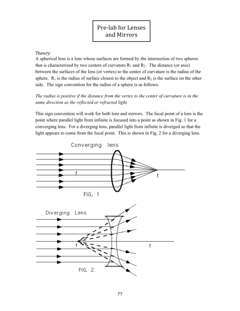
Pre-­‐lab for Lenses and Mirrors Theory: A spherical lens is a lens whose surfaces are formed by the intersection of two spheres that is characterized by two centers of curvature R1 and R2. The distance (or axis) between the surfaces of the lens (or vertex) to the center of curvature is the radius of the sphere. R1 is the radius of surface closest to the object and R2 is the surface on the other side. The sign convention for the radius of a sphere is as follows: The radius is positive if the distance from the vertex to the center of curvature is in the same direction as the reflected or refracted light. This sign convention will work for both lens and mirrors. The focal point of a lens is the point where parallel light from infinite is focused into a point as shown in Fig. 1 for a converging lens. For a diverging lens, parallel light from infinite is diverged so that the light appears to come from the focal point. This is shown in Fig. 2 for a diverging lens. 77 The focal distance for a converging lens can be calculated from knowing the index of refraction of the glass and the radii of the lens. The lens maker equation is as follows: (1) 1 1 1 = (n "1)( " ) f R1 R2 For a double convex lens, R1 is positive and R2 is negative. Therefore, by equation 1 the ! focal distance is positive and thus the lens is a converging lens. For a double concave lens, R1 is negative and R2 is positive. Therefore focal distance of double concave lens is negative. The graphical solution is shown in Fig. 3 for a converging lens and Fig. 4 for a diverging lens. The rays that are drawn are (l) light that comes in parallel to the axis are refracted such that they go to focal point for a converging lens or appear to come from the focal point for a diverging lens; (2) light that goes through the focal point is refracted to come out parallel; and (3) light that goes through the center of the lens goes straight through. In Fig. 3, the image is a real image and can be observed by placing a screen at that point. In Fig. 4, the image is a virtual image since the light appears to be coming from the image. A virtual image can be observed by looking directly into the lens. 78 A concave mirror reflects light such that light from infinite that comes in parallel to the axis reflects off the surface of the mirror and is focused at the focal point as shown in Fig. 5 Eqn. 3 below gives the relationship between the focal point and the radius f = R/2 (1) The graphical solution is shown in Fig. 6 for a concave mirror. The rays that are drawn are (l) light that comes in parallel to the axis are reflected to focal point (2) light that goes through the focal point is reflected to come out parallel; and (3) light that goes through the center of the curvature reflects straight back. The relationships between the object distance (do), the image distance (di), and the focal distance is given below. 1 1 1 + = do d i f (3) ! 79 The sign convention for do, di, and f are as follows: 1. The object distance (do) is positive if the distance from the object to the reflecting or refracting is in the same direction as the incident light. 2. The image distance (di) is positive if the distance from the reflecting or refracting surface to the image is in the same direction as the reflected or refracted light.. 3. The focal distance (f ) is positive if it’s for a converging lens or a concave mirror and is negative if it is for a diverging lens or a convex mirror. Graphical Solutions: Sketch the graphical solution for the following cases of lenses or mirrors. The arrow on the left indicates the object. In each case, state whether the image is real or virtual, erect or inverted, and enlarged or smaller. (a) Converging Lenses f f f f 80 f f (b) Diverging Lens (c) Concave Mirror 81 f f (d) Convex Mirrors f 82 Spherical Mirrors and Lenses If object distance is do and the image distance is di, then the focal length f is determined by Eqn 1. 1 1 1 + = do d i f (1) € Apparatus: 1. Optical bench 4. 200 mm and 100 mm converging lenses 2. Light source 5. -150 mm diverging lens 3. Screen 6. Concave mirror Procedure: A. Converging lens 1. Line up the light source, converging lens, and screen on the optical bench. Starting with the light source at one end and the lens 50 cm away. Adjust the screen to produce a sharp image. Record the object and image distance in the data table. Move the lens 5 cm closer to the light source and repeat the measurement. Repeat this procedure until the lens is too close to produce a real image. Plot 1/do versus 1/di. The slope of the line is -1 and the intercept is 1/f. Use this to find focal length of the lens and compare the result to the known value. 83 B. Concave Mirror 2. Place the light source at one end of optical bench. Place the mirror 50 cm away from the light source. The screen is a half a circle is placed between the light source and the mirror. Move the screen until the image is in focus. Record the object distance and the image distance in the data table. Move the mirror 5 cm closer and repeat the process. Repeat this procedure until the mirror is too close to produce a real image. Plot 1/do versus 1/di. The slope of the line is -1 and the intercept is 1/f. Use this to find focal length of the mirror and compare the result to the known value. C. Diverging Lens 3. To measure the focal length of a double concave lens requires a two-lens system. The concept used in a two-lens system is that the image produced by the first lens becomes the object for the second lens. Place a converging lens on the optical bench and focus a real image on the screen. Now in between the lens and the image, place the diverging lens. The object distance for the diverging lens is the negative of the distance from the diverging lens to the position of the original image. Now refocus the image on the screen. The image distance is the distance from diverging lens and the final image. Use Eqn. 1 to calculate the focal length of diverging lens. Change the position of the converging lens and repeat four more times. do2= Object Distance from second lens = Lo – di1 Lo = separation of lenses Diverging lens di2=Image Distance from second lens Converging lens di1=Image Distance from first lens D. Construction of a telescope 4. An astronomical telescope is constructed with two convex lenses. The ray diagram for this experiment is shown below. The separation of the two lenses is close to f1 + f2. Place the light source at one end of the optical bench. The 200 mm lens will be the objective lens and is placed closer to the screen. The 100 mm lens will be the eyepiece (which means it is closer to the eye.) The two-lens system is placed at the other end of 84 the optical bench. The separation between the lenses will start at 30 cm apart. To view the image, you must put you eye close to the eyepiece. Adjust the position of the objective lens to bring the image into focus. Describe the image you see. E. Construction of a microscope 5. A microscope magnifies an object that is close to the microscope. The ray diagram for microscope is shown below. The 100 mm lens is the objective lens and the 200 mm lens is the eyepiece. Place the lenses near one end of the optical bench and the light source in the middle of the bench. To focus the microscope, move the position of the objective lens until the image is in focus. Describe the image you see. 85 Data: A. Converging Lens Object Distance (do) Image Distance (di) 1/do 1/di Slope =________________ Intercept __________Known Focal length ___________ Experimental Focal length (1/Intercept) = ________Percent Error __________________ B. Concave Mirror Object Distance (do) Image Distance (di) 1/do 1/di Slope =________________ Intercept ____________Known Focal length ___________ Experimental Focal length (1/Intercept) = ________ Percent Error = ______________ 86 C. Diverging lens di1 Lo d02 =Lo –di1 di2 f2 Average focal length (f2) = ______________ Known value of focal length =______ Percent Error = _______________________ D. Comment on Construction of Telescope E. Comment of Construction of Microscope 87


