DIY Radio Frequency Detector Circuit: Build Your Own!
advertisement
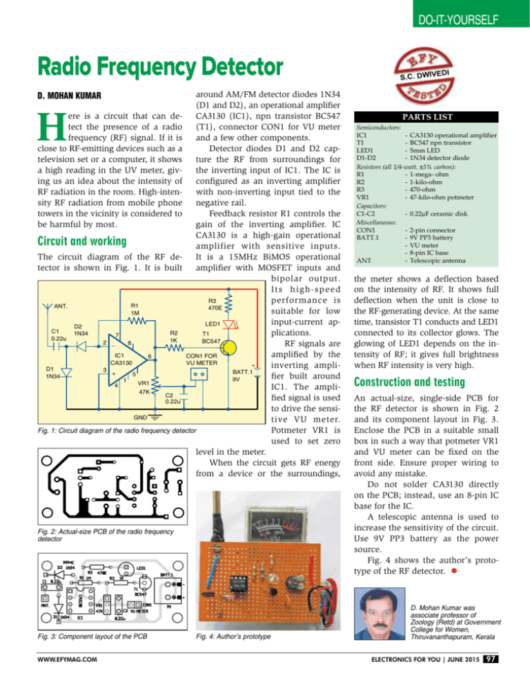
do-it-yourself Radio Frequency Detector around AM/FM detector diodes 1N34 (D1 and D2), an operational amplifier ere is a circuit that can de- CA3130 (IC1), npn transistor BC547 tect the presence of a radio (T1), connector CON1 for VU meter frequency (RF) signal. If it is and a few other components. Detector diodes D1 and D2 capclose to RF-emitting devices such as a ture the RF from surroundings for television set or a computer, it shows a high reading in the UV meter, giv- the inverting input of IC1. The IC is ing us an idea about the intensity of configured as an inverting amplifier RF radiation in the room. High-inten- with non-inverting input tied to the sity RF radiation from mobile phone negative rail. Feedback resistor R1 controls the towers in the vicinity is considered to gain of the inverting amplifier. IC be harmful by most. CA3130 is a high-gain operational Circuit and working amplifier with sensitive inputs. The circuit diagram of the RF de- It is a 15MHz BiMOS operational tector is shown in Fig. 1. It is built amplifier with MOSFET inputs and bipolar output. Its high-speed R3 performance is R1 ANT. 470E suitable for low 1M input-current apLED1 D2 C1 R2 1N34 plications. T1 7 0.22u 1K BC547 2 _ 8 RF signals are amplified by the IC1 CON1 FOR 6 CA3130 VU METER inverting ampliD1 3 BATT.1 + 5 1N34 fier built around 9V 1 VR1 4 IC1. The ampli47K C2 fied signal is used 0.22u to drive the sensiGND tive VU meter. Fig. 1: Circuit diagram of the radio frequency detector Potmeter VR1 is used to set zero level in the meter. When the circuit gets RF energy from a device or the surroundings, edi s.c. dwiv D. Mohan Kumar H Fig. 2: Actual-size PCB of the radio frequency detector Fig. 3: Component layout of the PCB www.efymag.com Fig. 4: Author’s prototype Parts List Semiconductors: IC1 - CA3130 operational amplifier T1 - BC547 npn transistor LED1 - 5mm LED D1-D2 - 1N34 detector diode Resistors (all 1/4-watt, ±5% carbon): R1 - 1-mega- ohm R2 -1-kilo-ohm R3 - 470-ohm VR1 - 47-kilo-ohm potmeter Capacitors: C1-C2 - 0.22µF ceramic disk Miscellaneous: CON1 - 2-pin connector BATT.1 - 9V PP3 battery - VU meter - 8-pin IC base ANT - Telescopic antenna the meter shows a deflection based on the intensity of RF. It shows full deflection when the unit is close to the RF-generating device. At the same time, transistor T1 conducts and LED1 connected to its collector glows. The glowing of LED1 depends on the intensity of RF; it gives full brightness when RF intensity is very high. Construction and testing An actual-size, single-side PCB for the RF detector is shown in Fig. 2 and its component layout in Fig. 3. Enclose the PCB in a suitable small box in such a way that potmeter VR1 and VU meter can be fixed on the front side. Ensure proper wiring to avoid any mistake. Do not solder CA3130 directly on the PCB; instead, use an 8-pin IC base for the IC. A telescopic antenna is used to increase the sensitivity of the circuit. Use 9V PP3 battery as the power source. Fig. 4 shows the author’s prototype of the RF detector. D. Mohan Kumar was associate professor of Zoology (Retd) at Government College for Women, Thiruvananthapuram, Kerala Electronics For You | June 2015 97


