C SERIES: APPLIED FLUID MECHANICS
MULTI-PUMP TEST RIG – C3MKII
©2015 Armfield Ltd
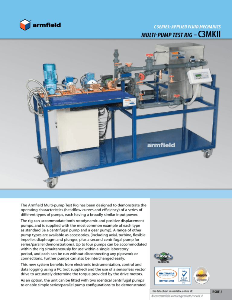
The Armfield Multi-pump Test Rig has been designed to demonstrate the
operating characteristics (headflow curves and efficiency) of a series of
different types of pumps, each having a broadly similar input power.
The rig can accommodate both rotodynamic and positive displacement
pumps, and is supplied with the most common example of each type
as standard (ie a centrifugal pump and a gear pump). A range of other
pump types are available as accessories, (including axial, turbine, flexible
impeller, diaphragm and plunger, plus a second centrifugal pump for
series/parallel demonstrations). Up to four pumps can be accommodated
within the rig simultaneously for use within a single laboratory
period, and each can be run without disconnecting any pipework or
connections. Further pumps can also be interchanged easily.
This new system benefits from electronic instrumentation, control and
data logging using a PC (not supplied) and the use of a sensorless vector
drive to accurately determine the torque provided by the drive motors.
™
enviro
PRODUCTS
As an option, the unit can be fitted with two identical centrifugal pumps
to enable simple series/parallel pump configurations to be demonstrated.
This data sheet is available online at:
discoverarmfield.com/en/products/view/c3/
ISSUE 2
DEMONSTRATION CAPABILITIES
DESCRIPTION
> Determining the performance of different
types of pumps at constant speed by
producing a set of characteristic curves
For rotodynamic pumps:
• Pressure head vs flow
• Power absorbed vs flow
• Pump efficiency vs flow
For positive displacement pumps:
• Flow vs pressure head
• Power absorbed vs pressure head
• Volumetric efficiency vs pressure head
> Determining the effect of speed on
the performance of pumps
> Understanding the difference between rotodynamic
pumps and positive displacement pumps
> Understanding the effect of system resistance
> Investigating the effect of suction
losses on a centrifugal pump
> Demonstration of the effect of running two
centrifugal pumps in series and parallel
(Requires C3-MkII-20SP)
> Understanding the characteristics of a
reciprocating pump (requires C3-MkII-25
or C3-MkII-26 and C3-MKII-40)
The equipment comprises a water reservoir,
and five pump positions, (four active).
Each pump position uses pipework and sensors
optimised to the type of pumps it is intended for.
Positions 1, 2a and 2b are optimised for high flows
at low heads, such as the rotodynamic pumps
whereas positions 3 and 4 are suitable for lower
flows but higher pressures, as obtained from
the positive displacement pumps. Note: Position
2a and Position 2b are mutually exclusive in as
much as they share the same motor drive.
To switch between any of the four installed
active pumps, (or series/parallel configuration)
is simple, requiring only isolating valve
changes and control panel selection.
To change over an installed pump for one of the other
options is still straightforward, but requires plumbing
changes (easy release fastenings), topping up the tank
with water (to replace any lost) and re-programming
some inverter settings. Additional pumps and options
can be purchased at any time, and fitted by the user.
A PC (not supplied) is used to set the required
speed of the pump(s) on test. A separate mimic
diagram for the selected pump(s) on test displays
the important measured and calculated variables.
The following table defines which types of
pumps are available for each position:
Position
Instrumented
Flow Capability
Instrumented
Pressure Capability
Pump Options
1
300 l/min
20m
-
Centrifugal (C3-MkII-20)
(included as standard)
2a
300 l/min
20m
-
Flexible Impeller (C3-MkII-23)
-
Second Centrifugal (C3-MkII-20SP) for
series/parallel operation
2b
300 l/min
3.4m
-
Axial (C3-MkII-22)
3
75 l/min
70m
-
Gear (C3-MkII-21) (included as standard)
4
75 l/min
70m
-
Turbine (C3-MkII-24)
-
Diaphragm (C3-MkII-25)
-
Plunger (C3-MkII-26)
ACCESSORIES
Pumps Available:
C3-MkII-20 Centrifugal Pump
(included in standard Supply)
A brass bodied centrifugal pump with plastic impellor
and stainless steel shaft. Maximum flow 137 l/min and
maximum head 9m.
C3-MkII-20SP Second Centrifugal Pump
(optional)
A second centrifugal pump, identical to C3-MkII-20,
and including the additional valves required to
perform a series/parallel pump demonstration.
C3-MkII-21 Gear Pump
(included in standard Supply)
A corrosion resistant bronze bodied gear pump, with
stainless steel shafts and bronze helical gears for quiet
operation. Maximum flow 13.7 l/min and maximum
head 60m (limited by system relief valve).
C3-MkII-22 Axial Flow Pump
(optional)
A purpose designed axial flow pump, housed in a clear
acrylic casing. Maximum flow 100 l/min and maximum
head 1.8m.
C3-MkII-23 Flexible Impellor Pump
(optional)
A bronze pump head with stainless steel shaft and
flexible impellor. Maximum flow 120 l/min at 3m head.
C3-MkII-24 Turbine Pump
(optional)
A straight bladed bronze turbine impellor with a
bronze pump body and stainless steel shaft. Maximum
flow 24 l/min and maximum head 30m.
C3-MkII-25 Diaphragm Pump
(optional, also requires C3-MkII-40
Volumetric Measurement System)
A diaphragm pump with uPVC wetted parts, with a
diaphragm 150mm (6 inch) diameter and a 25mm (1
inch) stroke. Maximum flow 5.8 l/min at a maximum
head of 60m (limited by system relief valve).
C3-MkII-26 Plunger Pump
(optional, also requires C3-MkII-40 Volumetric
Measurement System)
A plunger pump with stainless steel wetted parts, with
a bore of 34mm (1 3/8 inch) and a stroke of 25mm
(1inch). Maximum flow 5.3 l/min at maximum head of
60m (limited by system relief valve).
Each pump accessory comes on its own baseplate,
assembled complete with all pipes, valves and fittings
to enable it to be easily fitted to the C3-MkII. Different
types of fitting are used for different positions in order
to help prevent incorrect fitting.
C3-MkII-20SP
Second Centrifugal Pump
C3-MkII-22
Axial Flow Pump
C3-MkII-23
Flexible Impellor Pump
C3-MkII-24
Turbine Pump
C3-MkII-25 Diaphragm Pump
ORDERING SPECIFICATION
ACCESSORIES - CONTINUED
C3-MkII-40
Volumetric Measurement System
(essential for C3-MkII-25 and C3-MkII-26)
The reciprocating pumps (C3-MkII-25 and C3-MkII-26)
are not suitable for electronic flow measurement
due to the pulsating nature of the flow. To accurately
measure the flow rate from these pumps requires a
Volumetric Measurement System, where the volume of
water flowing over a period of time can be measured.
The C3-MkII-40 is an 8 litre water column, with
a vertical scale. The bottom of this column is
connected to the input of the reciprocating
pump, and the time taken for the water level to
change between two points is measured.
REQUIREMENTS
Electrical supply:
C3-MKII-A
220-240V/1ph/50Hz, 10A
C3-MKII-G
220-240V/1ph/60Hz, 10A
G version has optional 1.5kVA transformer available
to accommodate 120V/1ph/60Hz supply.
Computer:
A PC running Windows 98 or above with a
spare USB port (not supplied by Armfield).
Clean water:
120 litres (initial fill only, no permanent
connection required)
OVERALL DIMENSIONS
Height:1.50m
Width:2.20m
Depth:0.75m
SHIPPING SPECIFICATION
Gross weight Volume
500kg3.9m3
•A mobile self-contained Multi-Pump Test Rig,
containing all the services and instrumentation
for determining the characteristic curves of eight
different pumps at different speeds
•For rotodynamic pumps:
> Pressure head vs flow
> Power absorbed vs flow
> Pump efficiency vs flow
For positive displacement pumps:
> Flow vs pressure head
> Power absorbed vs pressure head
> Volumetric efficiency vs pressure head
•Contains five different pump positions (four
active at the same time). Digital readout enables
mounting of selected pump
•Centrifugal pump and gear pump supplied
as standard
•Axial pump, flexible impeller pump, turbine pump,
diaphragm pump, plunger pump and a second
centrifugal pump are all available as accessories
•Series/parallel pump demonstrations can
be performed with the second centrifugal
pump option
•Control valve incorporated upstream of each
pump (except axial pump) to demonstrate the
effect of suction loss on performance
•A PC (not supplied) is used to set the required
speed of the pump(s) on test. A separate mimic
diagram for the selected pump(s) on test displays
the important measured and calculated variables
•Electronic measurement of flow, pressure head,
suction head and motor torque
•Optional volumetric flow measurement system for
reciprocating pumps
•Data logging and educational software included
*
* Excluding DLMx range
Find us on YouTube!
www.youtube.com/user/armfieldUK
Follow us on Twitter, Facebook,
LinkedIn and
WordPress
Head Office:
Armfield Limited
Bridge House, West Street,
Ringwood, Hampshire.
BH24 1DY England
Telephone: +44 1425 478781
Fax: +44 1425 470916
E-mail: sales@armfield.co.uk
© 2015 Armfield Ltd. All Rights Reserved
Scan for website
FOR FURTHER INFORMATION ON THE ADVANCED FEATURES OF
THE SOPHISTICATED ARMFIELD SOFTWARE VISIT:
www.discoverarmfield.co.uk/data/armsoft/
U.S. Office:
Armfield Inc.
9 Trenton - Lakewood Road
Clarksburg NJ 08510
Tel/Fax: (609) 208-2800
E-mail: info@armfieldinc.com
We reserve the right to amend these specifications without prior notice. E&OE 03/14/3k
Correct at time of going to press.
Innovators in Engineering Teaching Equipment
learn more! www.armfield.co.uk


