CCDF determination – a comparison of two
advertisement

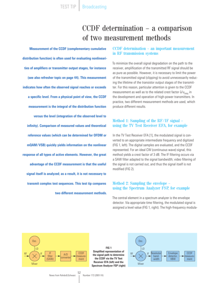
Broadcasting TEST TIP CCDF determination – a comparison of two measurement methods Measurement of the CCDF (complementary cumulative CCDF determination – an important measurement in RF transmission systems distribution function) is often used for evaluating nonlinearities of amplifiers or transmitter output stages, for instance (see also refresher topic on page 44). This measurement indicates how often the observed signal reaches or exceeds a specific level. From a physical point of view, the CCDF measurement is the integral of the distribution function To minimize the overall signal degradation on the path to the receiver, amplification of the transmitted RF signal should be as pure as possible. However, it is necessary to limit the power of the transmitted signal (clipping) to avoid unnecessarily reducing the lifetime of the transistor output stages of the transmitter. For this reason, particular attention is given to the CCDF measurement as well as to the related crest factor û/urms in the development and operation of high-power transmitters. In practice, two different measurement methods are used, which produce different results. versus the level (integration of the observed level to infinity). Comparison of measured values and theoretical reference values (which can be determined for OFDM or mQAM/VSB) quickly yields information on the nonlinear response of all types of active elements. However, the great advantage of the CCDF measurement is that the useful Method 1: Sampling of the RF/IF signal – using the TV Test Receiver EFA, for example In the TV Test Receiver EFA [1], the modulated signal is converted to an appropriate intermediate frequency and digitized (FIG 1, left). The digital samples are evaluated, and the CCDF represented. For an ideal CW (continuous wave) signal, this method yields a crest factor of 3 dB. The IF filtering occurs via a SAW filter adapted to the signal bandwidth; video filtering of the signal is not carried out, and thus the signal itself is not modified (FIG 2). signal itself is analyzed; as a result, it is not necessary to transmit complex test sequences. This test tip compares Method 2: Sampling the envelope – using the Spectrum Analyzer FSP, for example two different measurement methods. The central element in a spectrum analyzer is the envelope detector. Via appropriate time filtering, the modulated signal is assigned a level value (FIG 1, right). The high-frequency modula- Osc. Osc. LO IF RF IF filter (SAW) A/D converter CCDF measurement Mixer News from Rohde&Schwarz 52 FIG 1 Simplified representation of the signal path to determine the CCDF via the TV Test Receiver EFA (left) and the Spectrum Analyzer FSP (right) Number 172 (2001/III) LO IF Resolution bandwidth RF Mixer Envelope detector, VBW CCDF measurement tion is eliminated from the signal; only the “envelope” signal is used (FIG 2). The measured values of a pure CW signal always have the same amplitude; it has thus a crest factor of 0 dB. In the case of IF and video filtering, it must be ensured that the resolution bandwidth (RBW) and the video bandwidth (VBW) do not distort the signal: time BWResolution > BWSignal , BWVideo ≥ 3 · BWResolution . Differences in the results of the two methods FIG 2 Time characteristic of a modulated signal; yellow: original signal, yellow dots: measured values used by the TV Test Receiver EFA to calculate the CCDF (measurement method 1); red: measured values used by a spectrum analyzer (measurement method 2). The TV Test Receiver EFA analyzes the signal exactly as it is present at the RF input. According to its definition, a pure CW signal has a crest factor of 3 dB. The spectrum analyzer, on the other hand, analyzes the signal as it is present in the baseband (i.e. prior to modulation by the RF carrier), which in the case of the CW signal results in a DC voltage and consequently in a crest factor of 0 dB (ideally). Investigations have shown that the crest factors of both methods vary by 3 dB also in the case of random signals. However, the results of the CCDF measurements according to methods 1 and 2 cannot be converted one into the other simply by taking into account the difference of 3 dB. FIGs 3 and 4 show examples of the CCDF measurement using the Spectrum Analyzer FSP and the TV Test Receiver EFA. Conclusion Measuring the CCDF is a simple and effective method of determining the nonlinear characteristics of active elements. If the measurement of the CCDF is to be referred to the signal actually transmitted (instead of to the envelope), it is advisable to use the TV Test Receiver EFA. Christoph Balz REFERENCES [1] TV Test Receiver EFA: see article on page 34 in this issue [2] Spectrum Analyzer FSP: see article on page 20 in this issue ◆ The refresher topic “Measurements on MPEG2 and DVB-T signals” starting on page 44 covers the crest factor in detail News from Rohde&Schwarz 53 Number 172 (2001/III) FIG 3 CCDF measurement with the TV Test Receiver EFA (method 1). Signal: OFDM with 64QAM; both the measured values (continuous line) and the theoretical values of an ideal signal are shown. The limitation of the signal in the case of high crest factors is clearly discernible. FIG 4 CCDF measurement with the Spectrum Analyzer FSP (method 2). Same signal as in FIG 3; the crest factor (11.73 dB) is 3 dB lower than in the measurement according to method 1 (14.7 dB, FIG 3).


