LINEAGE™ 2000
ECS 6U and 12U Controllers
6U Model J85501E1
12U Model J85501E2
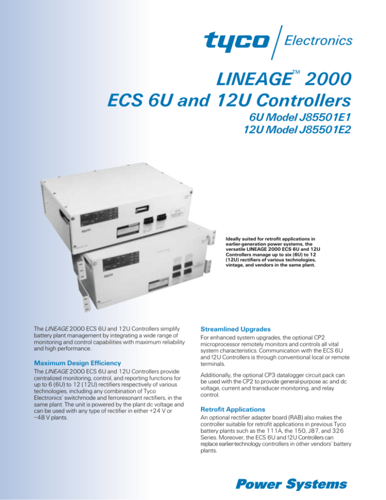
Ideally suited for retrofit applications in
earlier-generation power systems, the
versatile LINEAGE 2000 ECS 6U and 12U
Controllers manage up to six (6U) to 12
(12U) rectifiers of various technologies,
vintage, and vendors in the same plant.
The LINEAGE 2000 ECS 6U and 12U Controllers simplify
battery plant management by integrating a wide range of
monitoring and control capabilities with maximum reliability
and high performance.
Maximum Design Efficiency
The LINEAGE 2000 ECS 6U and 12U Controllers provide
centralized monitoring, control, and reporting functions for
up to 6 (6U) to 12 (12U) rectifiers respectively of various
technologies, including any combination of Tyco
Electronics’ switchmode and ferroresonant rectifiers, in the
same plant. The unit is powered by the plant dc voltage and
can be used with any type of rectifier in either +24 V or
–48 V plants.
Streamlined Upgrades
For enhanced system upgrades, the optional CP2
microprocessor remotely monitors and controls all vital
system characteristics. Communication with the ECS 6U
and !2U Controllers is through conventional local or remote
terminals.
Additionally, the optional CP3 datalogger circuit pack can
be used with the CP2 to provide general-purpose ac and dc
voltage, current and transducer monitoring, and relay
control.
Retrofit Applications
An optional rectifier adapter board (RAB) also makes the
controller suitable for retrofit applications in previous Tyco
battery plants such as the 111A, the 150, J87, and 326
Series. Moreover, the ECS 6U and !2U Controllers can
replace earlier-technology controllers in other vendors’ battery
plants.
Benefits
■
■
■
Simplified System Management
— Efficiently handles plant control,
monitoring, power alarm, and
status and reporting functions
through a centralized point of
operation.
■
Dip-switch settings for battery-ondischarge alarm, float/equalize highvoltage shutdown, and meter scaling
■
Automatic rectifier restart and reserve
ac engine transfer capability
Easy Installation and Maintenance
— Simplifies system setup and
servicing with modular and frontaccess design, connectorized
rectifier interface, and plug-in circuit
boards.
■
High-voltage shutdown testing
■
System normal and alarm LEDs,
major and minor fuse alarms, alarm
interface (form-C)
Fail-Safe Alarm System
— Responds instantly with alarms for
overcurrent, under/overvoltage,
open battery strings and battery on
discharge, minor/major fuse, and
ac and rectifier failure.
— Interfaces with standard office
alarms.
— LEDs indicate both normal status
and alarm status.
For plants requiring even more
sophisticated management capabilities,
the Controllers can be upgraded with
optional microprocessor and
datalogger circuit packs for enhanced
system features.
■
High Reliability
— Compatible with Bellcore technical
requirements and advisories.
■
Continuous Operation
— Loss of controller power, circuit
board removal/upgrade, or other
field maintenance will not disrupt
service to plant loads.
Features
■
Front-access design
■
The ECS 6U Controller monitors and
controls up to six rectifiers, and the
ECS 12U Controller monitors and
controls up to 12 rectifiers
■
Connectorized rectifier interface
■
Operate with or without batteries
(depending on rectifier capabilities)
■
Illuminated digital metering (±0.05%
voltmeter and ±0.5% ammeter
accuracy
■
Local initiated equalize charging
■
Extensive Statistical/Historical
Recording
— In-depth historical information,
including up to 128 plant and 50
rectifier alarm events, 12 equalize
charging events, and 16 control
relay status changes (sorted by
alarm type or date)
— Plant-load current statistics, hourly,
weekly, and monthly
— Plant voltage and current during
battery discharge
— Hourly average load currents over
any user-programmable 24-hour
period
— Datalogger channels statistics
— Historical data on installed power
equipment
■
Comprehensive Communications
— RS-232 port for local terminal or
printer
— Modem (300 bits per
second/1200 bits per second) and
RJ11 phone jack for remote
communications
— Pass-through communications to
the Microprocessor Control System
controller, the Remote Access
system, the OMNIpulse® system,
and the Intelligent Reserve Unit
— Periodic dial-out automatically
delivers plant statistics and
histories and datalogger readings
and statistics
— Automatic dial-out on occurrence
or retirement of alarms
— User-assigned alarms, delays, and
telephone numbers (compatible
with beepers)
— Note pad for message exchange by
maintenance personnel
Options
The additional capabilities can include
remote control, voice-response options,
system diagnostics and statistics,
general-purpose voltage and current
monitoring, and programmable control
relays.
Shunt isolator circuits and order wire
boards are available for use with certain
application-specific configurations.
Microprocessor (CP2)
■
Advanced System Management
— User-friendly, menu-driven software
— Multiple security levels: callback,
user, and superuser
— Remote rectifier surveill
capabilities (ON/STANDBY/
FAILURE modes)
— Remote rectifier ON/STAN
control*
— Remote equalizer control or b
charge initiation*
— Programmable for autom
maintenance reminders
— Rectifier sequence co
(facilitates transfer to an ac engine
alternator and allows userselectable delay times to sequence
ON/OFF states for individual
rectifiers or groups of rectifiers)
* These features can be hardware enabled/
disabled.
Datalogger (CP3)
■
General-Purpose Monitoring/Control
— Sixteen analog data-monitoring
channels with multiple range
(150 mV, 6 V, 60 V, and 150 V),
polarity, voltage selections (+dc,
–dc, and ac), and userprogrammable scale factors and
alarm thresholds
— Extensive alarm history and
statistical history on alarm
channels
— Eight form-C relay contacts with
programmable control logic for use
when generating alarms or
activating/deactivating other
equipment
— On/off control relay history (up to
16 events recorded per relay)
AKC1 Shunt Isolator Circuit
Pack
■
The AKC1 is required when the plant
shunt is located in the hot lead of the
discharge bus. Early Tyco plants and
some commercial plants have the
plant shunt in the hot lead. All Tyco
plants have the shunt in the ground
lead and do not require the AKC1
shunt isolator circuit pack.
The modular, front-access ECS 6U and 12U Controllers simplify
installation and maintenance and allow for convenient circuit-board
upgrades without interrupting service.
248A Order Wire Board
■
The 248A provides ringing to the
modem in the J85501E2 Controller.
It provides the ringing when a
contact closure is sent to the 248A
board from the order wire or an
equivalent system and eliminates the
need for a dedicated phone line.
This option should be ordered only
when the controller will be monitored
over the FT-Series G or a similar
embedded maintenance system.
LINEAGE 2000 ECS 6U and 12U Controllers, Model J85501E1 and J85501E2 Specifications
Battery Plant Alarm Voltage Ranges
High-Voltage Shutdown Thresholds
(adjustable to 0.5 V increments)
Equalize High-Voltage Shutdown
Thresholds (adjustable to
0.5 V increments)
Battery-On-Discharge Thresholds
(adjustable to 0.5 V increments)
Electrical and Thermal Specifications
Float Voltage Range
Operating Voltage Range
Input Power Range
Display Meter (four-digit, backlit LCD)
Range:
Voltmeter
Ammeter
Accuracy:
Voltmeter
Ammeter
Resolution
Plant Shunt
Alarm Contact Rating
Temperature
Physical Specifications
Height
Width
Depth
Weight
Frame Mounting Requirements,
Standard 23 in. and 26 in. Relay Rack:
Vertical Mounting Centers
Horizontal Mounting Centers
Environmental Specifications
Altitude
48 V Plant
Range
Accuracy
49.0 V to 60.0 V
±0.5 V
24 V Plant
Range
Accuracy
24.7 V to 29.75 V
±0.25 V
51.0 V to 60.0 V
±0.5 V
25.75 V to 30.75 V
±0.25 V
46.0 V to 57.5 V
±0.5 V
23.0 V to 28.50 V
±0.25 V
47.0 Vdc to 58.5 Vdc (48 Vdc nominal)
23.5 Vdc to 29.0 Vdc (24 Vdc nominal)
40.0 Vdc to 60.0 Vdc (48 Vdc nominal)
20.0 Vdc to 30.0 Vdc (24 Vdc nominal)
8 W to 16 W (depending on options)
0.00 V to ±60.00 V
0.0 A to 8000.0 A
±0.05% of full-scale reading
±0.5% of full-scale reading
±0.1 A for <1000 A
±1.0 A for >1000 A
50 mV at 300 A, 600 A, 1200 A, 2000 A, 2600 A,
4000 A, 6000 A, or 8000 A
60 Vdc, 1.0 A, form-C
0 °C to 50 °C (32 °F to 122 °F)
12U
9.0 in. (229 mm)
21.5 in. (546 mm)
15 in. (381 mm)
38 lb. (17.3 kg)
6U
7.0 in. (178 mm)
21.5 in. (546 mm)
15 in. (381 mm)
14 lb. (6.4 kg)
1.0 in. (25 mm)
22.32 in. (567 mm) for 23 in. (584 mm) rack mount
24.32 in. (618 mm) for alternate 26 in. (660 mm) rack mount
Humidity
–200 ft. to +13,000 ft. (–61 m to +3962 m)
For altitudes of 5000 ft.—13,000 ft., derate maximum temperature by
3.6 °F per 1000 ft. above 5000 ft.
For altitudes of 1524 m—3962 m, derate maximum temperature by
0.656 °C per 100 m above 1524 m
10% to 95% noncondensing
Safety/Standards Compliance
Electrostatic Discharge
Radiated and Conducted Emissions
Electromagnetic Immunity
IEC 801-2 Level 5 (15 kV) at 20% relative humidity
FCC Level A
10 V/m over the range of 20 MHz—2000 MHz
Outline Drawings
15 in.
(381 mm)
21.5 in.
(546 mm)
7 in.
(178 mm)
LINEAGE 2000 ECS 6U Controller Model J85501E1
15 in.
(381 mm)
21.5 in.
(546 mm)
9 in.
(229 mm)
LINEAGE 2000 ECS 12U Controller Model J85501E2
Ordering Information
For ordering information or assistance, please contact your Tyco Electronics Energy Solutions sales representative.
Tyco Electronics Power Systems, Inc.
3000 Skyline Drive, Mesquite, TX 75149, USA
+1-8
800-5
526-7
7819 FAX: +1-888-315-5182
972-2
284-2
2626, FAX: +1-972-284-2900)
(Outside U.S.A.: +1-9
http://power.tycoelectronics.com
Tyco Electronics Corporation reserves the right to make changes to the product(s) or information contained herein without notice. No liability is assumed as a result of
their use or application. No rights under any patent accompany the sale of any such product(s) or information.
©2001 Tyco Electronics Corporation, Harrisburg, PA. All International Rights Reserved.
Printed in U.S.A.
DS00-034LIN (Replaces DS97-461LIN and DS98-173LIN)
Printed on
Recycled Paper


