Thermodynamics Revision Guide
advertisement
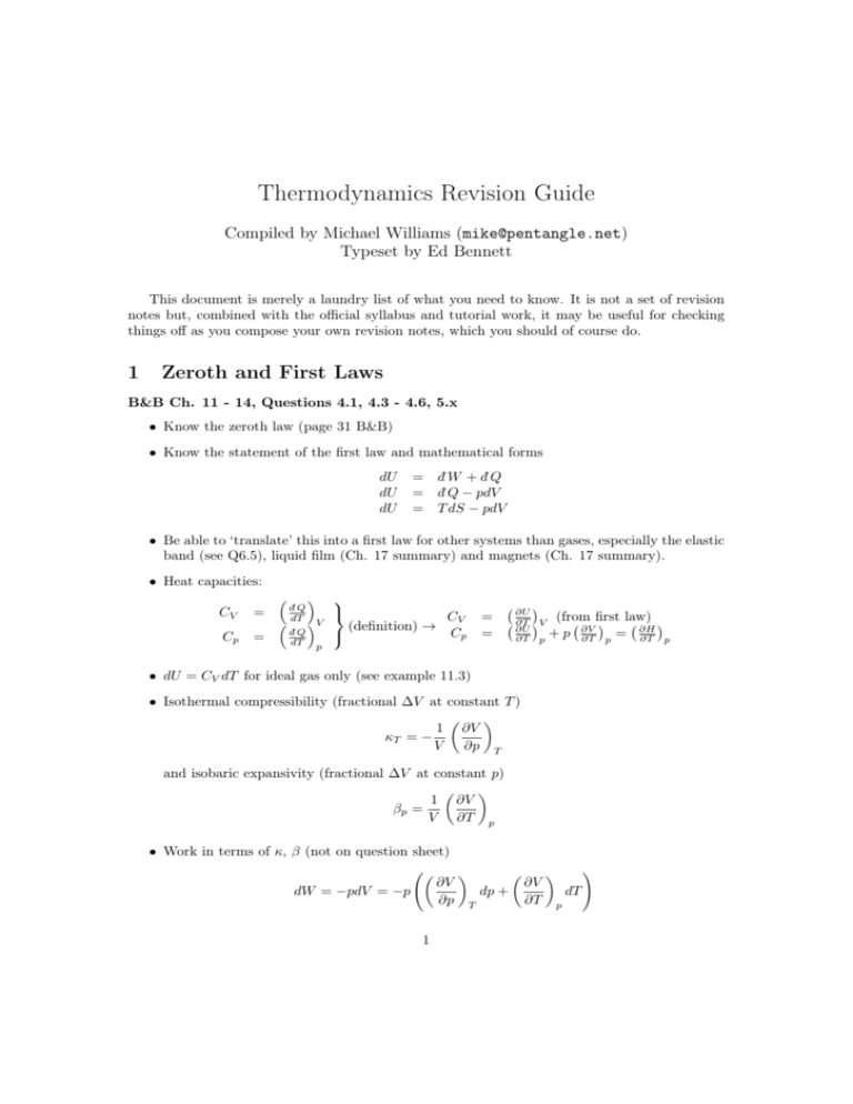
Thermodynamics Revision Guide Compiled by Michael Williams (mike@pentangle.net) Typeset by Ed Bennett This document is merely a laundry list of what you need to know. It is not a set of revision notes but, combined with the official syllabus and tutorial work, it may be useful for checking things off as you compose your own revision notes, which you should of course do. 1 Zeroth and First Laws B&B Ch. 11 - 14, Questions 4.1, 4.3 - 4.6, 5.x • Know the zeroth law (page 31 B&B) • Know the statement of the first law and mathematical forms dU dU dU = d¯W + d¯Q = d¯Q − pdV = T dS − pdV • Be able to ‘translate’ this into a first law for other systems than gases, especially the elastic band (see Q6.5), liquid film (Ch. 17 summary) and magnets (Ch. 17 summary). • Heat capacities: CV Cp = = d¯Q dT d¯Q dT V p CV (definition) → Cp = = ∂U ∂T V ∂U ∂T p (from first law) ∂H + p ∂V ∂T p = ∂T p • dU = CV dT for ideal gas only (see example 11.3) • Isothermal compressibility (fractional ∆V at constant T ) 1 ∂V κT = − V ∂p T and isobaric expansivity (fractional ∆V at constant p) 1 ∂V βp = V ∂T p • Work in terms of κ, β (not on question sheet) dW = −pdV = −p 1 ∂V ∂p dp + T ∂V ∂T ! dT p (we can do this because V is a function of state, so can be expressed as a total differential) p2 Z Z T2 κT V pdp − W = βp V pdT T1 p1 – Isothermal, dT = 0 p2 Z W = pV κT dp p1 N.B. for a solid, V, K ≈ const. ∴W ≈ 1 κT V p22 − p21 2 – Isobaric, dp = 0 Z T2 W =− pV βp dT T1 N.B. for a solid, V, β ≈ const. ∴ W ≈ −pV βp (T2 − T1 ) • ∂U ∂V T in measurable quantities = Cp −CV βp V − p (Q4.1) • Relationship between Cp and CV for ideal gas: Cp − CV = nR • Adiabat of an ideal gas: T V γ−1 = const. pV γ = const. • Isotherm of an ideal gas ∆Q = RT ln 2 V2 V1 Entropy (and use of Maxwell Relations) B&B Ch. 14, Questions 4.5 onwards, especially 4.5, 4.6, 5.1 • dS = d¯QTrev S is a function of state, so if your system is not undergoing a reversible change, choose one with the same end-points which does. This will have the same ∆S. • d¯Q = T dS (for reversible changes only) ⇒ dU = T dS − pdV • dS ≥ • d¯Q T for an irreversible change, ∴ d¯W > −pdV (irreversible) H = U + pV ∂2x ∂2x G = H − TS = ∂z∂y → four Maxwell relations + the fact that ∂y∂z F = U − TS 2 • You must be able to derive them, but the following mnemonic is useful in questions which do not explicitly ask you to prove a Maxwell relation, and when time is short — it allows ∂V etc. you to quickly quote one, e.g., ∂S p = ∂T ∂p S • Prove that for an ideal gas U is a function of T only: Write U (V, T ), prove ∂U ∂S ∂p =T −V =T −p=0 ∂V T ∂V T ∂T V ∂U ∂V T =0 • Change in S where S = S (T, V ) — useful when volume changes (e.g. Joule expansion) ∂S ∂S dS = dT + dV ∂T V ∂V T From a Maxwell relation ∂S ∂V = T ∂p ∂T V By definition CV = ∴ dS = ∂U ∂T =T V CV dT + T ∂P ∂T ∂S ∂T (1) V dV V Special case: Ideal gas pV = RT ⇒ S = CV ln T + R ln V + const. • Change in S where S = S (T, p) dS = Cp dT − T ∂V ∂T dp p (same method as above) • This allows calculation of Cp − CV for a non-ideal gas: ∂S T = Cp − T ∂T V And from equation 1 CV = Cp − T ∂V ∂T p ∂p ∂T = Cp − T V 2 ⇒ Cp − CV = ∂V ∂T " p ∂p ∂V T TV β ⇒ Cp > CV for everything! κT 3 ∂V ∂T # p 3 Second Law, Engines B&B Ch. 13, Questions 5.2, 5.3 • Second Law: No process can just convert heat into work. There must be waste heat. (This is Kelvin’s statement. Clausius’ statement, which can be shown equivalent, is not on the syllabus.) • Carnot Cycle (reversible) 1. Isothermal expansion at T1 , absorbs Q1 2. Adiabatic expansion T1 → T2 3. Isothermal compression at T2 , rejecting Q2 4. Adiabatic compression T2 → T1 Figure 1: Schematic diagram of a Carnot engine Figure 2: Graph of V against p for a Carnot engine 4 Figure 3: Graph of T against S for a Carnot engine • Efficiency (definition for an engine): η= W Q1 − Q2 Q2 = =1− Qin Q1 Q1 • Carnot’s theorem: There is no engine more efficient than a Carnot engine T1 γ−1 1 • Proof that Q is constant along an adiabat, Q2 = T2 - See Ex. 13.1. Need to prove that T V V2 and ∆Q = RT ln V1 on an isotherm for this. • Other engines: Q5.2, 5.3. Otto cycle, heat pump, refrigerator. 4 Expansions, Equations of State B&B Ch. 27, Questions 5.8, 6.1 - 6.3, 7.2 • Derivations of ∂T ∂V ∂T ∂V ∂T ∂p U S H ∂p −p Joule (Q5.8) T ∂T V ∂p = − C1V T ∂T Adiabatic V = C1p T ∂V Joule-Kelvin ∂T p − V = − C1V • Joule expansion Figure 4: Joule expansion d¯Q = 0 d¯W = 0 (vacuum) ∴ dU = 0 Process is irriversible, but can still use dU = T dS − pdV since initial and final states are what matters for U . 5 • Joule-Kelvin Figure 5: Joule-Kelvin expansion – Proof that H isconstant – Proof that ∂T = 0 for an ideal gas ∂p H = 0) and maximum inversion temperature (max – Concept of inversion curve ( ∂T ∂p H T at which ∂T = 0) ∂p H • For a gas obeying Dieterici’s equation of state Figure 6: T -p diagram for a Joule-Kelvin cooling process, showing the inversion curve – Maximum inversion temperature is where the inversion curve meets the T -axis - JouleKelvin process does not cool if you start above this temperature, regardless of T – The inversion curve is the line ∂T ∂p =0 H • Your gas might not obey this equation of state, so stop and think before you sketch the above! 6 • See Q6.2 and 6.3 for some example equations of state. Take note of the trick for evaluating ∂V , which is needed to calculate the Joule-Kelvin coefficient. For such gases it is usually ∂T p ∂p ∂p algebraically easier to evaluate ∂T and ∂V and note that V T ∂V ∂T p = − ∂p ∂T ∂p ∂V V T • Be comfortable with the critical point and reduced units (Q7.2) • Be able to describe liquefaction of helium by the Joule-Kelvin process – diagram, general description – pre-cooling using, for example, Joule expansion to get below the maximum inversion temperature – use a counter-current heat exchanger – for maximum efficiency, work on the inversion curve 5 Phase Changes • To prove the Clausius-Clapeyron equation, you must start by showing that a system in contact with a heat and pressure reservoir (which is the usual situation outside a laboratory) minimises its Gibbs energy. Figure 7: A system connected to a thermal and pressure reservoir Element of heat d¯Q moves into (or out of) system d¯Q ≤ T0 dS dU = d¯Q − p0 dV ∴ dU + p0 dV − T0 dS ≤ 0 d (U + pV − T S) ≤ 0 dG ≤ 0 i.e. system will undergo spontaneous changes reducing G, until equilibrium is reached (when d¯Q = T dS). For an alternative proof, see B&B 16.5. 7 • Next step is to show that this implies that two phases coexisting in equilibrium at a given T , p will have equal specific Gibbs energies: G = m1 g1 + m2 g2 dG = g1 dm1 + g2 dm2 at equilibrium in contact with a p, T reservoir dG = 0 From conservation of mass, dM = dm1 + dm2 = 0 ∴ g1 = g2 • Now we can prove the Clausius-Clapeyron equation! g1 (T, p) = g2 (T, p) g1 (T, p) + g1 (T + dT, p + dp) = g2 (T + dT, p + dp) ∂g1 ∂g2 ∂g2 ∂g1 dT + dp = g2 (T, p) + dT + dp ∂T p ∂p T ∂T p ∂p T ∂g2 ∂g2 ∂g1 ∂g1 dp − = − ∂T p ∂T p ∂p T ∂p T dT ∂G ∂G =V ∂p ∂T p = −S T (see B&B 16.4 - from the definition of Gibbs energy and the first law) ∴ (s2 − s1 ) = (V2 − V1 ) dp dT Let ` = heat transfer of phase change = T (s2 − s1 ) ∴ dp ` = dT T (V2 − V1 ) • Typical phase boundaries Figure 8: A p-T diagram for a typical substance. 8 • But for water, the liquid-solid boundary has a negative gradient: Figure 9: Phase diagram for water A large enough increase of pressure on such a solid can melt it. This is offen erroneously cited as the reason ice skates glide on a film of liquid water. As can be seen above, the gradient of the liquid-solid boundary is very steep, and realistic pressures are not sufficient. The actual mechanism for ice skates is more complicated - see, for example, http://amasci.com/miscon/ice.txt and http://www.ccmr.cornell.edu/education/ ask/index.html?quid=1138. 9


