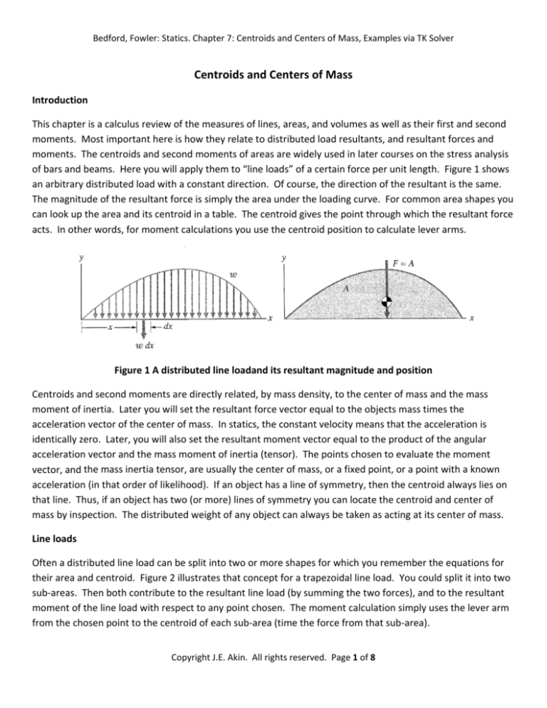
Bedford, Fowler: Statics. Chapter 7: Centroids and Centers of Mass, Examples via TK Solver Centroids and Centers of Mass Introduction This chapter is a calculus review of the measures of lines, areas, and volumes as well as their first and second moments. Most important here is how they relate to distributed load resultants, and resultant forces and moments. The centroids and second moments of areas are widely used in later courses on the stress analysis of bars and beams. Here you will apply them to “line loads” of a certain force per unit length. Figure 1 shows an arbitrary distributed load with a constant direction. Of course, the direction of the resultant is the same. The magnitude of the resultant force is simply the area under the loading curve. For common area shapes you can look up the area and its centroid in a table. The centroid gives the point through which the resultant force acts. In other words, for moment calculations you use the centroid position to calculate lever arms. Figure 1 A distributed line loadand its resultant magnitude and position Centroids and second moments are directly related, by mass density, to the center of mass and the mass moment of inertia. Later you will set the resultant force vector equal to the objects mass times the acceleration vector of the center of mass. In statics, the constant velocity means that the acceleration is identically zero. Later, you will also set the resultant moment vector equal to the product of the angular acceleration vector and the mass moment of inertia (tensor). The points chosen to evaluate the moment vector, and the mass inertia tensor, are usually the center of mass, or a fixed point, or a point with a known acceleration (in that order of likelihood). If an object has a line of symmetry, then the centroid always lies on that line. Thus, if an object has two (or more) lines of symmetry you can locate the centroid and center of mass by inspection. The distributed weight of any object can always be taken as acting at its center of mass. Line loads Often a distributed line load can be split into two or more shapes for which you remember the equations for their area and centroid. Figure 2 illustrates that concept for a trapezoidal line load. You could split it into two sub‐areas. Then both contribute to the resultant line load (by summing the two forces), and to the resultant moment of the line load with respect to any point chosen. The moment calculation simply uses the lever arm from the chosen point to the centroid of each sub‐area (time the force from that sub‐area). Copyright J.E. Akin. All rights reserved. Page 1 of 8 Bedford, Fowler: Statics. Chapter 7: Centroids and Centers of Mass, Examples via TK Solver Figure 2 Distributed loads can be split into alternate regions Distributed line loads can often be approximated by a simple polynomial. Figure 3 gives relations for the area and centroid of a region under a polynomial segment. It includes a rectangular region (n=0, a=bh, x_g=b/2), a triangle (n=1, a=bh/2, x_g= 2b/3), a parabolic segment (n=2, a=bh/3,x_g=3b/4) among the general relations. Similar relations for the area above the curve are also given. Note that Figure 1 could have been split into two such areas. Or, it could have been viewed as a rectangular load minus two polynomial end segments. Figure 3 Useful equations for a polynomial line load segment Example 7.7 This beam, in Figure 4, has a constant vertical line load of 400 N/m between points A and B. Its vertical leg has a trapezoidal horizontal load of 800 N/m at the bottom tapering down to 400 N/m at the top. The vertical leg load could be split into two triangular loads, a triangle and a rectangular load, or be integrated directly with calculus. the text shows the second option, but the TK example (in Figures 5 and 6) will use the first option. Figure 4 A beam with two distributed line loads The rectangular vertical distributed load, between points A and B, is 400 ⁄
6
2,400 . ⁄2
Relative to point B, its lever arm is 3 . The rectangular load on the vertical leg has the same magnitude and length. Thus, it will have the same magnitude (but is directed horizontally), and the same Copyright J.E. Akin. All rights reserved. Page 2 of 8 Bedford, Fowler: Statics. Chapter 7: Centroids and Centers of Mass, Examples via TK Solver relative lever arm from the top. The triangular load on the vertical leg is calculated from the top point, to make the equations in Figure 3 apply. The resultant horizontal force is /2
400 ⁄
6 /2
1,200 . Its lever arm, from the top is 2 ⁄3
4 . Figure 4 (right) shows those same two lever arms measured from the bottom of the vertical leg. Generally, you need to develop the distributed line load resultant(s) value and location before you write the equilibrium equations. The resultant distributed load , or moment with respect to point B is: _
_
2400 3
2400 6
3
1200 6
4
2,400
Likewise, you could have split the vertical leg line load into two triangles. One varies from 800N/m at the bottom to zero at the top, while the second varies from 400 N/m at the top to zero at the bottom. The first /2
800 ⁄
6 /2 2,400 at 2 ⁄3
4 (2m above B). triangle has a resultant of /2
400 ⁄
6 /2 1,200 at 2 ⁄3
4 above point B. The smaller triangle has Clearly, the net resultant force is the same (3,600 N) as is the final moment with respect to B for both line loads: _
2400 3
2400 6 4
1200 4
2,400
. Figure 5 Rule sheet for beam with two line loads Copyright J.E. Akin. All rights reserved. Page 3 of 8 Bedford, Fowler: Statics. Chapter 7: Centroids and Centers of Mass, Examples via TK Solver As a comment, Figure 5 contains the resultant force and moment of a trapezoidal load that is easily obtained from Figure 2 (try it). Note that the line loads per unit length can have either positive or negative signs. However, for line loads with mixed signs you have to be alert to avoid division by zero. Thus, for the first time, a rule for the centroid of the leg line load includes an if‐then‐else statement to avoid possible division by zero. The text loading values are used in Figure 6 and the outputs match the support loads of the text. Figure 6 Variables sheet for beam with two line loads By referring to Figure 2, you should note that the general line load can be split into a pure couple effect combined with a centered force effect. This concept is sketched in Figure 7. That is a common way to view such loads, especially when studying beams. Sometimes the pressure causes only a couple. Figure 7 A line load is often split into a couple combined with a centered force Copyright J.E. Akin. All rights reserved. Page 4 of 8 Bedford, Fowler: Statics. Chapter 7: Centroids and Centers of Mass, Examples via TK Solver To illustrate the concept of a line load causing only a pure couple consider Figure 8. There the line load on AB is omitted, and the leg line load has opposite signs at each end. That is, the leg has a line load that vanishes at the midpoint of the leg. Thus, it looks like two triangular loads. One is to the right on the top half of the leg and an equal and opposite one on the lower half of the leg. The resultant applied loading is a pure couple. Therefore, you should expect the supports to respond with an equal and opposite couple. Figure 8 shows that result in that support point B pushes up with a force while the vertical force at A is downward and has the same value. Being separated by the distance L_AB, they form the resisting couple. There is no horizontal force at A because the resultant centered force was zero. Figure 8 Line load forming a pure couple Example 7.16 The problem as presented has a diagonal symmetry as indicated by the geometry on the left of Figure 9. The TK example is stated in a more general form where the two segments of the bar have different lengths. The mass (and weight) per unit length is taken as constant. Here, the x‐centroid is found by requiring the moment of the weight of the pieces to equal the moment of the total weight. The y‐centroid is found by the composite object (line) theorem. The corresponding rules are given in Figure 10. Copyright J.E. Akin. All rights reserved. Page 5 of 8 Bedford, Fowler: Statics. Chapter 7: Centroids and Centers of Mass, Examples via TK Solver Figure 9 Weight loading of a L‐shaped bar The mass per unit length is related to the total mass. That yields the weight of each leg section. Of course, Ay must balance the total weight for the given support conditions. The roller force, B, will depend on the relative lengths of the two legs. Figure 11 shows the results for the text data where the two leg lengths were each one meter. If you bent the same bar into a form where the upper leg was only half a meter, you should expect the reaction at B to increase for two reasons. First, its (vertical) lever arm has been reduced. Secondly, the lever arm of the weight W_AC has increased. Indeed, Figure 12 shows that holding the mass constant and specifying the horizontal length L_AC to one and a half meters, the system finds the vertical length, L_CB, as expected. That change in bend point increases the force at the roller by a factor of 2.5 to about 1,472 N. If you needed to limit that force to 1,000 N then you could input that into your TK model and solve for L_AC after giving it a starting guess. (Try that change. The new length is about 1.31 m, as given in Figure 13.) Figure 10 L‐shape bar with unequal leg lengths Copyright J.E. Akin. All rights reserved. Page 6 of 8 Bedford, Fowler: Statics. Chapter 7: Centroids and Centers of Mass, Examples via TK Solver Figure 11 Output for a symmetrical bar Figure 12 Unequal length legs change the roller force Copyright J.E. Akin. All rights reserved. Page 7 of 8 Bedford, Fowler: Statics. Chapter 7: Centroids and Centers of Mass, Examples via TK Solver Figure 13 Limiting the roller force determines the new shape, L_AC Copyright J.E. Akin. All rights reserved. Page 8 of 8


