Exp 1 Cross Flow Heat Exchanger
advertisement
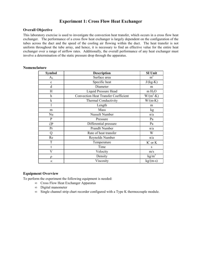
Experiment 1: Cross Flow Heat Exchanger Overall Objective This laboratory exercise is used to investigate the convection heat transfer, which occurs in a cross flow heat exchanger. The performance of a cross flow heat exchanger is largely dependent on the configuration of the tubes across the duct and the speed of the cooling air flowing within the duct. The heat transfer is not uniform throughout the tube array, and hence, it is necessary to find an effective value for the entire heat exchanger over a range of airflow rates. Additionally, the overall performance of any heat exchanger must involve a determination of the static pressure drop through the apparatus. Nomenclature Symbol AS c d H h k l m Nu P ∆P Pr Q Re T t V ρ µ Description Surface area Specific heat Diameter Liquid Pressure Head Convection Heat Transfer Coefficient Thermal Conductivity Length Mass Nusselt Number Pressure Differential pressure Prandlt Number Rate of heat transfer Reynolds Number Temperature Time Velocity Density Viscosity SI Unit m2 J/(kg-K) m m H 2O W/(m2-K) W/(m-K) m kg n/a Pa Pa n/a W n/a °C or K s m/s kg/m3 kg/(m-s) Equipment Overview To perform the experiment the following equipment is needed: • Cross Flow Heat Exchanger Apparatus • Digital manometer • Single channel strip chart recorder configured with a Type K thermocouple module. Figure 1. The cross flow heat exchanger apparatus. Figure 2. Schematic diagram of the cross flow heat exchanger test section. The cross flow heat exchanger apparatus is shown in Figure 1 and consists of a fan and duct assembly mounted on a rolling frame. The centrifugal fan draws air into the 125 x 125 mm duct through a flared entry and exhausts upward through the vertical duct above the fan unit. Mounted in the middle of the duct assembly is a clear acrylic test section. The air speed through the duct is varied by the position of a sliding throttle plate at the top of the vertical duct. The air speed in the duct is determined by measuring the static and total pressures of the flow using pressure taps and a manometer. Two static pressure taps are provided at the front and rear of the test section (on the bottom side). A moveable total pressure probe can be used to measure the total pressure at several points in the working section. A schematic diagram of the test section is shown in Figure 2. One or more acrylic rods (12.5 mm diameter) may be inserted into the test section with their axes at right angles to the direction of flow (i.e. the rod is said to be in cross flow). Any space provided in the test section may be occupied by an element consisting of a pure copper rod carried between two extension rods of plastic compound. The element may be heated to a maximum of about 80 °C by withdrawing it from the test section and inserting it into the low voltage electric heater mounted to the frame under the duct section near the fan. Important parameters of the copper element are given in the table below: Diameter Length Weight 12.5 mm 94.90 mm 106.9 grams Basic Functionality of the Device One of the acrylic rods is removed from the test section, while the copper element brought to approximately 80 °C in the heater. A desired airspeed is set for the test section, and the copper element is quickly removed from the heater and slid into the empty position in the test section, where it immediately cools. The temperature of the copper element is recorded using the strip chart so that a time history of the cooling process is obtained. The apparatus and instrumentation provide the following data: Symbol t T T∞ Description elapsed time Temperature of the copper rod Temperature of inlet air SI Unit s °C °C General Operating Procedure a) Configure the acrylic rods in the test section as desired. Remove the rod in the position to be tested. Use the black plugs to seal any unused holes in the test section (i.e. in places where rods are not going to be used). b) The digital manometer can be used to measure differential pressure (by using both ports) or static pressure relative to the ambient (by using only one port). In any case zero out the unit with no pressure differential across the two ports. c) Turn on the strip chart recorder and verify all settings. Adjust the span and chart speed as appropriate. Verify the attenuation is turned to the CAL position. Test the pen. d) Turn the heater on and insert the copper element. Monitor the temperature of the element and do not exceed 80 °C. e) Adjust the throttle valve to the desired setting and turn on the fan unit. f) Measure the total and static pressure upstream of the test section to determine the airspeed in the inlet duct. (To measure the pressure drop across the test section: attach the manometer to the upstream and downstream static pressure taps on the bottom of the test section) g) When the copper element is about 80 °C, verify the strip chart recorder is ready to record data (i.e. put the pen down and turn the paper feed ON. Insert the copper element quickly into the test section in the desired location and monitor the temperature as it cools to within 5-10 °C of the ambient air temperature. h) Turn off the fan unit, stop the strip chart paper feed and return the copper element to the heater to prepare for the next test. i) Repeat steps (c) – (g) to obtain additional data. General Theory Part 1. Air Speed Calculation Using Pitot Tube In many cases, pressure is indicated in the equivalent column height of a liquid, (sometimes known as a pressure head) usually water for gas (air) flow, or mercury for liquid (water) flow. The hydrostatic pressure created in a column of any liquid is given by: P = ρgH (1) Hence, when a pressure is given in terms of height, e.g. inches H2O or mm Hg, then it can be converted to a pressure using equation (1). This pressure head or liquid height is historically related to the differential height for the two columns of the liquid in a U-Tube manometer. A Pitot Tube measures both the total (or stagnation) pressure and the static pressure in an air flow. The velocity of the air is related to the difference of these two pressures by: 2 ( Ptotal − Pstatic ) (2) V= ρ air The pressure in equation (2) is in terms of force over area, so a pressure measured in liquid column height must be converted. For example, if the pressure is given in terms of inches H2O then using equation (1) in equation (1) gives: V= 2 ( H total − H static ) ρ water g ρ air (3) To obtain the density of ambient air, use the ambient pressure and temperature and the Ideal Gas Law: V= 2 ( H total − H static ) ρ water g Pambient R g Tambient where Rg is the Universal Gas Constant and equal to: Rg = 287 (J/kg-K) (4) for air only! Warning: CHECK YOUR ENGINEERING UNITS! Pressure heads may need to be converted to standard length dimensions and temperature will need to be converted to Rankine or Kelvin. Part 2. Using Lumped Capacitance Method for an Immersed Body During the experiment a copper rod is heated above the ambient air temperature and then inserted into the working section of the heat exchanger apparatus, upon which the copper rod immediately begins to cool by forced convection heat transfer from the surface of the copper rod to the air flowing pass it. The heat transfer is transient and in a finite amount of time, the copper rod will cool to the temperature of the air flowing over it, at which time, heat transfer will no longer occur. Since the copper rod is relatively thin with an appreciable surface area from which heat can be transferred, an assumption can be made that the temperature of the copper rod is uniform throughout, and that the temperature of the copper rod is a function of time only. Using this assumption, lumped system analysis can be used to analyze the heat transfer from the copper rod to the air passing over it. The governing equation for the heat transfer is obtained using the conservation of energy, that is, the change of energy within the body must be equal to the net exchange of energy in and out of the body, hence, − h AS (T −T∞ ) = mc dT dt (5) t < 0: Ti Temperature of the rod t ≥ 0: T( t ) The boundary conditions for Eqn. (5) are: (5a) To solve equation (5) for the temperature, T, it is useful to define, θ = (T - T∞ ) and mc h AS which yields equation (5) as: θi = (Ti - T∞ ) dθ = −θ dt (6) which can be solved using separation of variables and integrating from the initial condition T(t=0) = Ti or θi = (Ti - T∞ ) giving: θ mc ln i = t h Al θ or hA T − T∞ θ = = exp − S θ i Ti − T∞ mc t (7) Equation (7) can be used to find the theoretical temperature-time history for a known geometry and convection coefficient. Using experimental data, Equation (7) can also be used to determine the value of inside of the bracket of the exponential function. A convenient method to do this to do the following: 1. Perform a linear transformation of Equation (7) giving, hA ln θ = − S t + ln θ i mc (8) 2. Plot the data with ln( θ ) on the y-axis and time, t, on the x-axis, so it will form a linear trend. 3. Fit a linear trend line to the data forcing the intercept to cross the vertical axis at a value of ln( θi ) 4. The slope of the line represents the value of the terms in the bracket in Equation (8). From this the experimental value of h can be determined if the geometry is known, or the necessary geometry for a specific value of h can be determined. Experimental Configurations: There are several phenomena that can be studied using the cross flow heat transfer apparatus. Your instructor may require you to investigate one or more of the following sets of experimental objectives. Check with your instructor to determine what you need to do! Effect of (Column) Position Within the Array Columns 1 & 2 / Heated bar on columns 1 & 2. Investigate the effect of the column position on the heat transfer from the cylinder by reporting the Nusselt Number as a function of the Reynolds Number. As a minimum, obtain data at five air speeds through the heat exchanger. Develop an appropriate correlation for the effective performance in the heat exchanger (i.e. a single correlation using all of the experimental data to get an average value for the whole unit. Also, compare the experimental data to correlation(s) available in the literature. An important performance parameter for any heat exchanger is the static pressure drop across the unit for one or both of the fluids passing through the unit. For a range of airspeeds through the heat exchanger, investigate the effect of the air speed on the static pressure drop. Show the results graphically. Effect of Tube Array Configuration Columns 2 & 4 / Heated bar on columns 2 & 4. Investigate the heat transfer from the cylinder by reporting the Nusselt Number as a function of the Reynolds Number. As a minimum, obtain data at five air speeds through the heat exchanger. Configure the heat exchanger as a two column staggered array. Develop an appropriate correlation for the effective performance of each configuration (i.e. an average value for each configuration). Also, compare the experimental data to correlation(s) available in the literature. An important performance parameter for any heat exchanger is the static pressure drop across the unit for one or both of the fluids passing through the unit. For a range of airspeeds through each configuration, investigate the effect of the air speed on the static pressure drop. Show the results graphically. Effect of Column Spacing on Heat Transfer Columns 1-2, Heated bar on column 2, Columns 1-4, Heated bar on column 4. Investigate the heat transfer from the cylinder in the tube array by reporting the Nusselt Number as a function of the Reynolds Number. As a minimum, obtain data at five air speeds through the heat exchanger. Set up the heat exchanger in a two-column configuration. Test the cylinder in the back column near the center row positions. Vary the distance of the second column to investigate the effect of the column spacing on the heat transfer. Develop an appropriate correlation for the effective performance of each configuration (i.e. an average value for each configuration). Also, compare the experimental data to correlation(s) available in the literature. An important performance parameter for any heat exchanger is the static pressure drop across the unit for one or both of the fluids passing through the unit. For a range of airspeeds through each configuration, investigate the effect of the air speed on the static pressure drop. Show the results graphically.
