Heat exchanger lab - Texas A&M University
advertisement
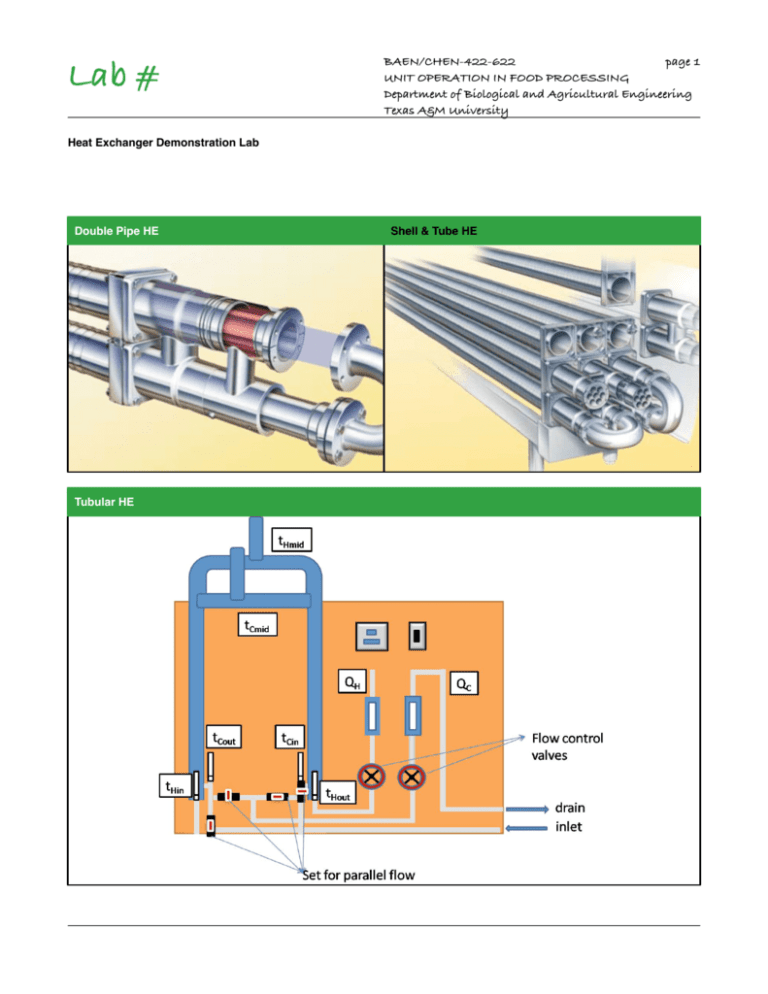
Lab # BAEN/CHEN-422-622! page 1 UNIT OPERATION IN FOOD PROCESSING Department of Biological and Agricultural Engineering Texas A&M University Heat Exchanger Demonstration Lab Double Pipe HE Tubular HE Shell & Tube HE Lab 4 BAEN/CHEN-422-622! page 2 UNIT OPERATION IN FOOD PROCESSING Department of Biological and Agricultural Engineering Texas A&M University Heat Exchanger Demonstration Lab Summary The process of heat exchange between two fluids that are at different temperatures and separated by a solid wall occurs in many engineering applications. The device used to implement this exchange is termed a heat exchanger, and specific applications may be found in space heating and air-conditioning, power production, waste heat recovery, and food & chemical processing. 4.1 Background Heat exchangers are typically classified according to flow arrangement and type of construction. The simplest heat exchanger is one for which the hot and cold fluids move in the same or opposite directions in a concentric tube (or double-pipe construction). In the parallel flow arrangement the hot and cold fluids enter at the same end, flow in the same direction, and leave at the same end. In the counterflow arrangement the fluids enter at opposite ends, flow in opposite directions, and leave at opposite ends. There are other configurations, like cross-flow, shell-and-tube, finned and unfinned, among others. In this lab we are going to demonstrate the working principles of a concentric tube heat exchanger. The knowledge of the principles of heat transfer within the heat exchanger are needed in order to design and/or evaluate the performance of a heat exchanger. In a concentric tube heat exchanger: Heat power emitted [W] = Qh ρh Cph (Thin-Thout) Heat power absorbed [W] = Qc ρc Cpc (Tcin-Tcout) (Properties must be evaluated separately for the cold and hot side using the average temperature) Heat power lost = heat power emitted - heat power absorbed Efficiency η = [(heat absorbed )/(heat power emitted)]x100 Log mean temperature difference [oC] = ΔTm=(ΔT1-ΔT2)/[ln(ΔT1/ΔT2)] Overall heat transfer coefficient [W/m2oC] = U = q/(AΔTm) = = (heat power absorbed)/(heat transmission area ΔTm) In a concentric tube heat exchanger, the equations for calculating the performance characteristics (heat power emitted, heat power absorbed, heat power lost, efficiency, logarithmic mean temperature difference, and overall heat transfer coefficient) are contained in Chapter 3. Lab 4 BAEN/CHEN-422-622! page 3 UNIT OPERATION IN FOOD PROCESSING Department of Biological and Agricultural Engineering Texas A&M University Temperature efficiencies of the heat exchanger are: a) for the cold medium ηc = [(Tcout-Tcin)/(Thin-Tcin)]x100 b) for the hot medium ηh = [(Thin-Thout)/(Thin-Tcin)]x100 c) mean temperature efficiency ηmean = (ηc + ηh)/2 Temperature efficiency is an actual indicator of the actual heat transfer taking place in the heat exchanger as a percentage of the maximum possible heat transfer that would take place if infinite surface area were available. 4.2 Objectives: 1.) Compare the working principles of a concentric tube heat exchanger operating under parallel and counter flow conditions. 2.) Demonstrate the effect of hot water temperature variation, and flow rate variation on the performance characteristics of a concentric tube heat exchanger. 4.3 Apparatus: Concentric tube heat exchanger with two flowmeters, and thermometers in the inlet and outer side of the hot and cold fluid ( L = 1.6 m and A = 0.069 m2). BAEN/CHEN-474! page 4 UNIT OPERATION IN FOOD PROCESSING Department of Biological and Agricultural Engineering Texas A&M University Lab 4 Experiment A : Parallel and Counterflow Group 1 The Lab heat exchanger Set equipment under parallel flow conditions according to the front panel of heat exchanger, and once conditions have stabilized, take the temperature readings for the inlet and outlet thermometers of both the cold and hot fluid. Repeat the experiment using counter flow set-up on heat exchanger. Initial variables to be used: Controlled hot water T 60 C Hot water flow rate Qh 2000 cm3/min Cold water flow rate Qc 1000 cm3/min Experiment B : Changing the hot water flow rate Group 2 The Lab heat exchanger Set equipment under counter flow conditions according to the front panel of heat exchanger maintaining the hot water inlet temperature at 60°C, and while changing the hot water flow rate, take the temperature readings for the inlet and outlet thermometers of both the cold and hot fluid once conditions have stabilized. Initial values to be used: Controlled hot water T 60 C Hot water flow rate Qh 2000 cm3/min Cold water flow rate Qc 1000 cm3/min BAEN/CHEN-474! page 5 UNIT OPERATION IN FOOD PROCESSING Department of Biological and Agricultural Engineering Texas A&M University Lab 4 Experiment C : Changing the hot water temperature Group 3 Set equipment under counter flow conditions according to the front panel of heat exchanger maintaining the hot water flow rate at 2000 cm3/min and cold water at 1000 cm3/min, and while changing the hot water temperature, take the temperature readings for the inlet and outlet thermometers of both the cold and hot fluid once conditions have stabilized. The Lab heat exchanger BAEN/CHEN-474! page 6 UNIT OPERATION IN FOOD PROCESSING Department of Biological and Agricultural Engineering Texas A&M University Lab 4 Results for change in direction Readings T h-in [C] T h-mid [C] T h-out [C] T c-in [C] T c-mid [C] T c-out [C] Power emitted [W] Power absorbed [W] Power lost Efficiency ΔTm U [W] [%] [C] [W/m2K] parallel flow counterflow Calculation Flow direction parallel flow counterflow Results for change in flow rate Qh [cm3/min] T h-in [C] T h-out [C] T c-in [C] T c-out [C] 1000 2000 3000 4000 Calculations Qh [cm3/min] 1000 2000 3000 4000 Power emitted [W] Power absorbed [W] Power lost [W] Efficiency [%] ΔTm U [C] [W/m2K] BAEN/CHEN-474! page 7 UNIT OPERATION IN FOOD PROCESSING Department of Biological and Agricultural Engineering Texas A&M University Lab 4 Results for change in temperature Control set [C] T h-in [C] T h-out [C] T c-in [C] T c-out [C] 45 50 55 60 Calculations Control set [C] Power emitted [W] Power absorbed [W] Power lost [W] Efficiency [%] ΔTm U [C] [W/m2K] 45 50 55 60 Utilize appropriate conversion factors to ensure consistency of units when making calculations. 4.5 Results and Discussion 1.) Make all the calculations in the tables. 2.) Discuss the effect of fluid direction in the efficiency, and overall heat transfer coefficient of the heat exchanger. 3.) Discuss the effect of temperature change, and flow rate variation in the efficiency, and overall heat transfer coefficient of the heat exchanger.
