Application
Note: 50731
FT-IR Analysis of Used Lubricating Oils –
General Considerations
Michael C. Garry, John Bowman, Thermo Fisher Scientific, Madison, WI, USA
Introduction
Key Words
• Antifreeze
• Antiwear
Additive
• Diesel Fuel
• Gasoline
Infrared spectroscopy is a widely used technique for the
analysis of lubricating oils. The Thermo Scientific Nicolet™
FT-IR spectrometer, coupled with OMNIC™ Integra™
software, provides modern laboratories with an intuitive
package for routine infrared analysis of liquid samples.
This application note details the application and the
parameters used to derive the highest quality data.
• Lubricants
Parameter
of Interest
Spectral
Location
(approx. cm-1)
• Oxidation
• Soot
Infrared analysis of used lubricants provides useful molecular
information about the changes in a lubricant and the
mechanical compartment being lubricated. This makes the
technique an effective trending and screening tool in
modern maintenance programs. Information from infrared
analysis can be used to complement data obtained by
elemental analysis techniques, such as atomic emission or
inductively coupled plasma (ICP) spectroscopy. In addition,
it may reduce or replace the analysis requirements for
certain traditional techniques that are tedious and time
consuming. It must be stressed that infrared analysis is a
trending and screening tool for multiple parameters of
interest in lubricants and mechanical systems.
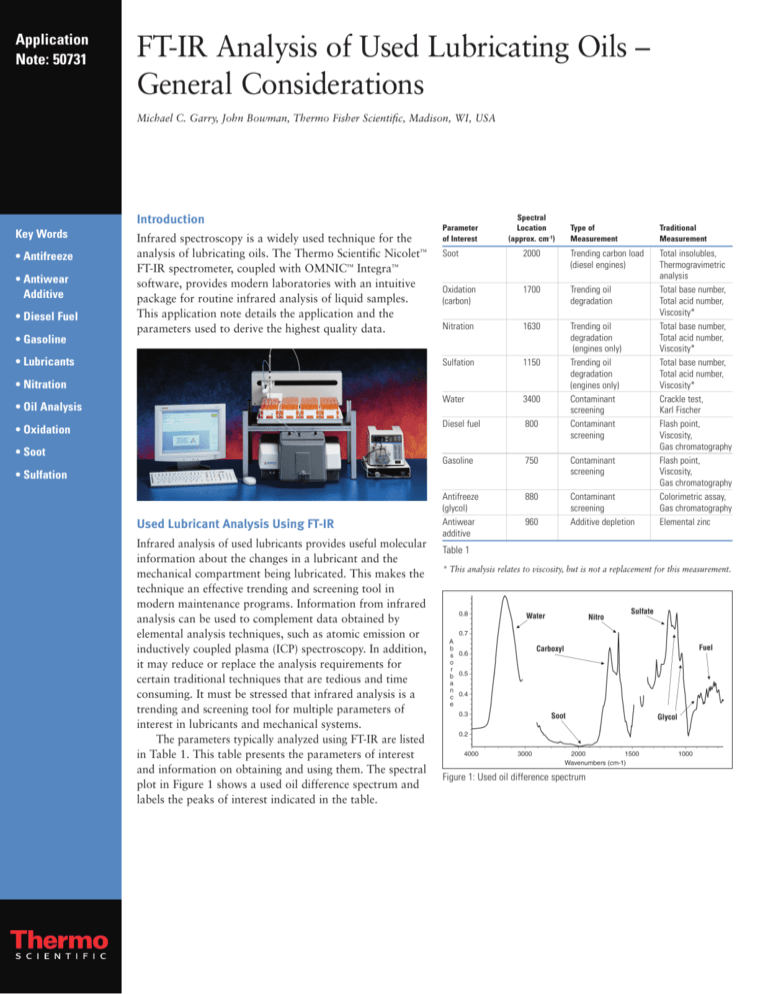
The parameters typically analyzed using FT-IR are listed
in Table 1. This table presents the parameters of interest
and information on obtaining and using them. The spectral
plot in Figure 1 shows a used oil difference spectrum and
labels the peaks of interest indicated in the table.
Total insolubles,
Thermogravimetric
analysis
Total base number,
Total acid number,
Viscosity*
Total base number,
Total acid number,
Viscosity*
Total base number,
Total acid number,
Viscosity*
Crackle test,
Karl Fischer
Flash point,
Viscosity,
Gas chromatography
Flash point,
Viscosity,
Gas chromatography
Colorimetric assay,
Gas chromatography
Elemental zinc
2000
Trending carbon load
(diesel engines)
Oxidation
(carbon)
1700
Trending oil
degradation
Nitration
1630
Sulfation
1150
Water
3400
Diesel fuel
800
Trending oil
degradation
(engines only)
Trending oil
degradation
(engines only)
Contaminant
screening
Contaminant
screening
Gasoline
750
Contaminant
screening
Antifreeze
(glycol)
Antiwear
additive
880
Contaminant
screening
Additive depletion
• Sulfation
Used Lubricant Analysis Using FT-IR
Traditional
Measurement
Soot
• Nitration
• Oil Analysis
Type of
Measurement
960
Table 1
* This analysis relates to viscosity, but is not a replacement for this measurement.
Figure 1: Used oil difference spectrum
Analysis Considerations
As a trending and screening tool, FT-IR analysis of used
lubricants has limitations and must be applied with
appropriate measures to assure proper generation and
interpretation of data. First and foremost, numeric results
from all of the parameters being determined (with the
exception of soot), are affected by the molecular fingerprint
of the base lubricant and additive package. That is to say,
the additives and base oil have spectral features that interfere
with the peaks that develop as the lubricant is contaminated
or oxidized during use. The magnitude of the peaks that
develop are typically smaller than, or of similar magnitude
to, those found in the unused oil. This can be seen in
Figure 2, which displays a plot of a new oil, the same oil
used and the subtraction result (difference spectrum). The
difference spectrum is shown with a much expanded y-scale.
New Oil
Used Oil
Difference
2100
1900
1700
1300
1500
Wavenumber
1100
900
700
Figure 2: New oil reference spectrum subtraction
Figure 3 shows four different new oils. The plot
shows the differences in spectral features resulting from
the variation in base oils and additives used to make the
lubricants. These differences must be taken into account,
or they will cause errors in the numeric values obtained
from the analysis. Because of this, spectral subtraction of
the proper new oil reference spectrum is applied to obtain
correct used oil analysis results.
OMNIC Integra software provides advanced features
for the creation and maintenance of custom, quantitative
new oil reference libraries. In addition, when the new oil
is not known, the autoreference feature is available to
search a library for the best selection before reference
subtraction. However, this option should not be used
routinely since it may generate incorrect results, particularly
for antifreeze, fuel and water, depending on the reference
library contents. It should only be used if a reference
spectrum is unobtainable.
Table 2 provides a relative sensitivity rating of the
analysis components to the correct reference oil being
used. Components with higher sensitivity will give a more
significant error in the numeric values obtained when the
incorrect reference is used. In the case of water, antifreeze,
diesel fuel and gasoline, using the incorrect reference
may produce false positive indications, or cause these
components to not be detected. This is particularly true
when autoreferencing is used because an unknown used
oil with a contaminant is being searched against a clean
oil library. The presence of the contaminant can make the
spectrum of the unknown used oil appear more like
another type of lubricant than the correct new oil reference.
Component
Relative Sensitivity
soot
oxidation
nitration
sulfation
water
glycol
fuel
gasoline
ZDDP
insensitive
fairly insensitive
fairly insensitive
fairly insensitive
fairly sensitive
very sensitive
extremely sensitive
extremely sensitive
extremely sensitive
Table 2
1850
1650
1450
1250
1050
Wavenumber
Figure 3: Infrared spectra of four different new oils
850
650
Considerations for Specific Analysis Parameters of Interest
Please refer to Figure 1 and Table 1 for this discussion.
Soot Particles
Fuel Residue
Suspended soot is the result of the incomplete combustion
of fuel. This is usually only a consideration in diesel
engines but could be indicative of carburetor or injector
problems with other fuel systems. While it has no specific
frequency of absorption in the infrared spectrum, soot
causes a shift in the baseline of the spectrum due to
absorption and scattering of light. Since there are no other
spectral features in the region around 2000 cm-1, this area
is used to assess the level of soot in a sample. The baseline
shift caused by soot is affected by the amount of soot
present and the effective particle size. The effective particle
size is a resultant of the nature of the combustion system
and the dispersants in the oil. This makes it difficult to
directly assess the quantity of soot, so factors that relate
the amount of soot to the infrared value must be established
with the engines and lubricants of interest.
The measurement of fuel residues or raw fuel is difficult
by any method. The main difference between the fuel and
base oil is in molecular weight or boiling range and the
percentage of aromatic materials. Fuel has a lower boiling
range and significantly higher percentage of aromatic
material. Conventional methods make use of the lower
boiling range, while the infrared approach examines the
aromatic content to indicate if fuel is present. The spectral
features around 800 cm-1 are used for this purpose.
The accuracy of measurement by any technique is
strongly affected by the standard material used to calibrate
the instrument and the level to which the fuel is evaporated
within the engine crankcase. The infrared technique has
the additional requirement of needing to match the newoil reference properly, as discussed earlier. It is the change
in base oil aromatic level that is the major factor leading
to errors from reference mismatch. Gasoline contamination detection is less problematic than detection for diesel
fuel because of the higher aromatic content of gasoline.
Even though calibrations are provided in the OMNIC
Integra software, it is best if fuel is calibrated by the laboratory using the system. In any case, it is important to use
at least one other independent test, such as viscosity, flash
point, or gas chromatography to confirm an indication of
fuel presence by FT-IR analysis.
Carbonyl Oxidation Products
The broad feature centered around 1730 cm-1 is due to the
presence of carbonyl-containing degradation products of
oil. These have been identified as lactones, esters, aldehydes,
ketones, carboxylic acids and salts, as well as others. The
broadness of the peak is because of the wide variety of
materials present. The point of maximum intensity will
vary as the oil and conditions of its use are changed. The
increase in peak height that occurs as the number of hours
the oil has been run in the engine increases has a greater
significance in the measurement of degradation than total
acid number (TAN) or viscosity.
Nitrogen Oxidation Products
The sharp feature at 1630 cm-1 is the result of nitrogen
oxide fixation into the oil. The materials that create this
feature are due mostly to nitrate esters. Nitrogen fixation
products are most significant in gasoline and natural gas
engines and some diesel systems that use exhaust gas
recirculation.
Sulfur Oxidation Products
Another broad spectral feature, centered around 1150 cm-1,
is the result of sulfate compounds as well as overlap with
oxidation products. Sulfate material is a result of the
introduction of sulfur from fuels or from the oxidation of
sulfur from the base oil and additives. This band is a fairly
specific measure of over basing additive consumption and
relates to total base number (TBN).
Water and Glycol Contamination
These two contaminants have characteristic absorptions in
the infrared that make their detection possible near the
0.1% level. While this is not as sensitive as some other
techniques, it is at a level where problems from the presence
of these contaminants in the crankcase could begin. Water
is detected as a broad feature, centered around 3400 cm-1
that is caused by the hydroxyl (-OH) group. Glycol has a
characteristic peak around 880 cm-1 as well as peaks at
1040, 1080, and 3400 cm-1. The peak at 880 cm-1 is used
to quantify because it is not subject to interferences to the
same extent as the other bands. The other peaks in the
spectrum related to glycol are used to confirm its presence.
Glycol will interfere with the quantification of the
water level when present, but the converse is not true.
Therefore, when glycol is present, water cannot be reliably
quantified using FT-IR. This is not considered a problem
because the presence of glycol has a greater significance to
engine performance. As with fuel, it is extremely important
to use at least one other test to confirm that water or glycol
are present in a used-oil sample. Water can be confirmed
by the crackle test or the Karl Fischer test. Glycol presence
can be confirmed by a colorimetric test, and corroborated
with elemental analysis results of sodium and boron.
Reporting of Data
The values determined from the infrared spectrum for the
components discussed in the preceding section are reported
in different ways because of the nature of the materials
present. The following values are reported by OMNIC
Integra software:
• Oxidation, nitration and sulfation components are not
reported as concentration values, because there are
many different chemical compounds formed that
contribute to the measured absorption. Since no single
product is formed, standard materials are not available
to generate the calibration curves needed to relate
absorbance to concentration. Absorbance values related
to the thickness of sample exposed to light are reported.
The units used for reporting are absorbance per 0.1
millimeter (ABS/0.1 mm), which relates directly to the
peak intensities observed in the difference spectrum of
a used oil. The information for these components is
most useful in trend analysis.
• The carbon particles that form soot do not cause
localized absorption. Instead, an offset of the spectral
baseline due to light scattering and absorption is
observed. The magnitude of this offset is determined by
the particle size of the soot as well as its concentration.
The particle size observed is affected by the engine type
and lubricant. ABS/0.1 mm values related to the thickness
of sample exposed to light are reported as well.
• Antiwear additive, typically various forms of zinc
dithiodiphosphate, is reported in ABS/0.1 mm the same
as the above oxidation components. However, the
antiwear additive is reported as a negative value because
in the used-oil difference spectrum the peak goes in the
opposite direction of other peaks in the spectrum. This
is due to the depletion of the additive compared to the
original reference oil.
In practice, the approach taken to make use of the
absorbance values for the uncalibrated components is to
note their increase over time within an engine. From a
plot or table of the change in absorbance with time,
judgments about when to change the lubricant can be
made. This is where experience with used lubricant analysis
comes into play.
Table 3 provides an explanation of the units reported
by the software with some typical and high results.
Component
Limit of
Units
Typical
Detection
Result
High Result
soot
oxidation
nitration
sulfation
antiwear*
diesel fuel
gasoline
glycol
water
ABS/0.1 mm
ABS/0.1 mm
ABS/0.1 mm
ABS/0.1 mm
ABS/0.1 mm
weight %
weight %
weight %
weight %
NA
0.02
0.02
0.02
-0.02
2.0
1.0
0.1
0.1
0.22
0.1
0.1
0.1
-0.05
NA
NA
NA
NA
0.70
1.0
1.0
1.0
-1.0
6.0
6.0
0.3
0.3
Table 3
* Antiwear is reported as a negative value since it represents the depletion of
a material. “NA” means “not applicable”
Reference
Used Lubricating Oil Analysis manual, P/N 269-069403, Thermo Fisher
Scientific, 2003.
• Fuel, water, glycol, and gasoline are reported in percent
values from calibrations with standards. The calibrations
that are provided in the software for diesel fuel and
gasoline may not accurately reflect the fuels in use in a
particular region of the world. Because of this, these
components should be calibrated with locally generated
standards. In the case of water and glycol, these materials
are typically very consistent. These components should
not need to be routinely calibrated locally because of the
difficulty of making and analyzing standards.
In addition to these
offices, Thermo Fisher
Scientific maintains
a network of representative organizations
throughout the world.
Africa
+43 1 333 5034 127
Australia
+61 2 8844 9500
Austria
+43 1 333 50340
Belgium
+32 2 482 30 30
Canada
+1 800 530 8447
China
+86 10 5850 3588
Denmark
+45 70 23 62 60
Europe-Other
+43 1 333 5034 127
France
+33 1 60 92 48 00
Germany
+49 6103 408 1014
India
+91 22 6742 9434
Italy
+39 02 950 591
Japan
+81 45 453 9100
Latin America
+1 608 276 5659
Middle East
+43 1 333 5034 127
Netherlands
+31 76 587 98 88
South Africa
+27 11 570 1840
Spain
+34 914 845 965
Sweden / Norway /
Finland
+46 8 556 468 00
Switzerland
+41 61 48784 00
UK
+44 1442 233555
USA
+1 800 532 4752
www.thermo.com
©2007 Thermo Fisher Scientific Inc. All rights reserved. All trademarks are the property of Thermo Fisher Scientific Inc. and its subsidiaries.
Specifications, terms and pricing are subject to change. Not all products are available in all countries. Please consult your local sales representative for details.
Thermo Electron Scientific
Instruments LLC, Madison, WI
USA is ISO Certified.
AN50731_E 11/07M
Part of Thermo Fisher Scientific


