Poster2_Arrhythmia_Recognition_e
advertisement
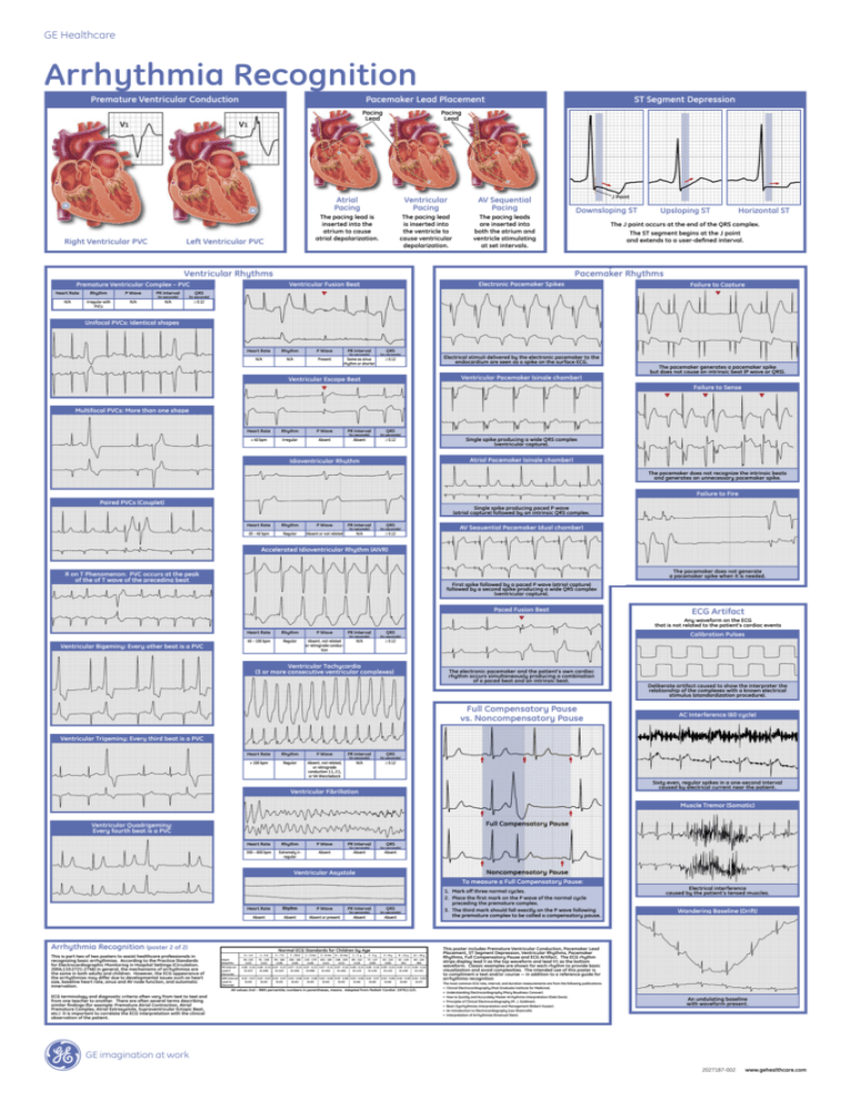
GE Healthcare Arrhythmia Recognition Premature Ventricular Conduction V1 Pacemaker Lead Placement Pacing Lead V1 Right Ventricular PVC Left Ventricular PVC ST Segment Depression Pacing Lead Atrial Pacing Ventricular Pacing AV Sequential Pacing The pacing lead is inserted into the atrium to cause atrial depolarization. The pacing lead is inserted into the ventricle to cause ventricular depolarization. The pacing leads are inserted into both the atrium and ventricle stimulating at set intervals. Ventricular Rhythms P Wave PR Interval (in seconds) (in seconds) N/A Irregular with PVCs N/A N/A ≥ 0.12 Upsloping ST Horizontal ST The J point occurs at the end of the QRS complex. The ST segment begins at the J point and extends to a user-defined interval. Electronic Pacemaker Spikes Ventricular Fusion Beat Rhythm Downsloping ST Pacemaker Rhythms Premature Ventricular Complex – PVC Heart Rate J Point Failure to Capture QRS Unifocal PVCs: Identical shapes Heart Rate Rhythm P Wave PR Interval N/A N/A Present Same as sinus rhythm or shorter (in seconds) QRS (in seconds) Electrical stimuli delivered by the electronic pacemaker to the endocardium are seen as a spike on the surface ECG. ≥ 0.12 Ventricular Pacemaker (single chamber) Ventricular Escape Beat The pacemaker generates a pacemaker spike but does not cause an intrinsic beat (P wave or QRS). Failure to Sense Multifocal PVCs:More More than one shape Multifocal PVCs: than one shape Heart Rate Rhythm P Wave PR Interval (in seconds) (in seconds) QRS < 40 bpm Irregular Absent Absent ≥ 0.12 Single spike producing a wide QRS complex (ventricular capture). Atrial Pacemaker (single chamber) Idioventricular Rhythm The pacemaker does not recognize the intrinsic beats and generates an unnecessary pacemaker spike. Failure to Fire Paired PVCs (Couplet) Single spike producing paced P wave (atrial capture) followed by an intrinsic QRS complex. Heart Rate Rhythm P Wave PR Interval 20 – 40 bpm Regular Absent or not related N/A (in seconds) QRS AV Sequential Pacemaker (dual chamber) (in seconds) ≥ 0.12 Accelerated Idioventricular Rhythm (AIVR) The pacemaker does not generate a pacemaker spike when it is needed. R on T Phenomenon: PVC occurs at the peak of the of T wave of the preceding beat of the preceding beat First spike followed by a paced P wave (atrial capture) followed by a second spike producing a wide QRS complex (ventricular capture). Paced Fusion Beat ECG Artifact Any waveform on the ECG that is not related to the patient’s cardiac events Ventricular Bigeminy: Every other beat is a PVC Heart Rate Rhythm P Wave PR Interval 40 – 100 bpm Regular Absent, not related or retrograde conduction N/A (in seconds) QRS Calibration Pulses (in seconds) ≥ 0.12 Ventricular Tachycardia (3 or more consecutive ventricular complexes) The electronic pacemaker and the patient’s own cardiac rhythm occurs simultaneously producing a combination of a paced beat and an intrinsic beat. Full Compensatory Pause vs. Noncompensatory Pause Deliberate artifact caused to show the interpreter the relationship of the complexes with a known electrical stimulus (standardization procedure). AC Interference (60 cycle) Ventricular Trigeminy: Every third beat is a PVC Heart Rate Rhythm P Wave PR Interval (in seconds) (in seconds) QRS > 100 bpm Regular Absent, not related, or retrograde conduction 1:1, 2:1, or VA Wenckeback N/A ≥ 0.12 Sixty even, regular spikes in a one-second interval caused by electrical current near the patient. Ventricular Fibrillation Muscle Tremor (Somatic) Ventricular Quadrigeminy: Every fourth beat is a PVC Heart Rate Rhythm P Wave PR Interval 300 – 600 bpm Extremely irregular Absent Absent (in seconds) QRS (in seconds) Absent Ventricular Asystole To measure a Full Compensatory Pause: Heart Rate Rhythm P Wave PR Interval (in seconds) (in seconds) Absent Absent Absent or present Absent Absent Arrhythmia Recognition (poster 2 of 2) This is part two of two posters to assist healthcare professionals in recognizing basic arrhythmias. According to the Practice Standards for Electrocardiographic Monitoring in Hospital Settings (Circulation. 2004;110:2721-2746) in general, the mechanisms of arrhythmias are the same in both adults and children. However, the ECG appearance of the arrhythmias may differ due to developmental issues such as heart size, baseline heart rate, sinus and AV node function, and automatic innervation. ECG terminology and diagnostic criteria often vary from text to text and from one teacher to another. There are often several terms describing similar findings (for example: Premature Atrial Contraction, Atrial Premature Complex, Atrial Extrasystole, Supraventricular Ectopic Beat, etc.) It is important to correlate the ECG interpretation with the clinical observation of the patient. 1. Mark off three normal cycles. 2. Place the first mark on the P wave of the normal cycle preceding the premature complex. 3. The third mark should fall exactly on the P wave following the premature complex to be called a compensatory pause. QRS Normal ECG Standards for Children by Age Heart Rate/Min 0–1d 1–3d 3–7d 7 – 30 d 1 – 3 mo 3 – 6 mo 6 – 12 mo 1–3 y 3–5y 5–8y 8 – 12 y 12 – 16 y 94 -155 (122) 91 - 158 (122) 90 - 166 (128) 106 - 182 (149) 120 - 179 (149) 105 - 185 (141) 108 - 169 (131) 89 - 152 (119) 73 - 137 (109) 65 - 133 (100) 62 - 130 (91) 60 - 120 (80) PR Interval Lead II (Seconds) 0.08 - 0.16 0.08 - 0.14 0.07 - 0.15 0.07 - 0.14 0.07 - 0.13 0.07 - 0.15 0.07 - 0.16 0.08 - 0.15 0.08 - 0.16 0.09 - 0.16 0.09 - 0.17 0.09 - 0.18 (0.107) (0.108) (0.102) (0.100) (0.098) (0.105) (0.106) (0.113) (0.119) (0.123) (0.128) (0.135) QRS Interval Lead V5 (Seconds) 0.02 - 0.07 0.02 - 0.07 0.02 - 0.07 0.02 - 0.08 0.02 - 0.08 0.02 - 0.08 0.03 - 0.08 0.03 - 0.08 0.03 - 0.07 0.03 - 0.08 0.04 - 0.09 0.04 - 0.09 (0.05) (0.05) (0.05) (0.05) (0.05) (0.05) (0.05) (0.06) (0.06) (0.06) (0.06) (0.07) All values 2nd – 98th percentile; numbers in parentheses, means. Adapted from Pediatr Cardiol. 1979;1:123. Electrical interference caused by the patient’s tensed muscles. Wandering Baseline (Drift) This poster includes Premature Ventricular Conduction, Pacemaker Lead Placement, ST Segment Depression, Ventricular Rhythms, Pacemaker Rhythms, Full Compensatory Pause and ECG Artifact. The ECG rhythm strips display lead II as the top waveform and lead V1 as the bottom waveform. Classic examples are shown for each rhythm to provide basic visualization and avoid complexities. The intended use of this poster is to compliment a text and/or course — in addition to a reference guide for arrhythmia recognition The most common ECG rate, interval, and duration measurements are from the following publications: • Clinical Electrocardiography (Post Graduate Institute for Medicine). • Understanding Electrocardiography (Mary Boudreau Conover). • How to Quickly and Accurately Master Arrhythmia Interpretation (Dale Davis). • Principles of Clinical Electrocardiography (M. J. Goldman). • Basic Dysrhythmias Interpretation and Management (Robert Huszar). • An Introduction to Electrocardiography (Leo Shamroth). • Interpretation of Arrhythmias (Emanual Stein). An undulating baseline with waveform present. GE imagination at work 2027187-002 www.gehealthcare.com
