Perceiving Depth and Size
advertisement
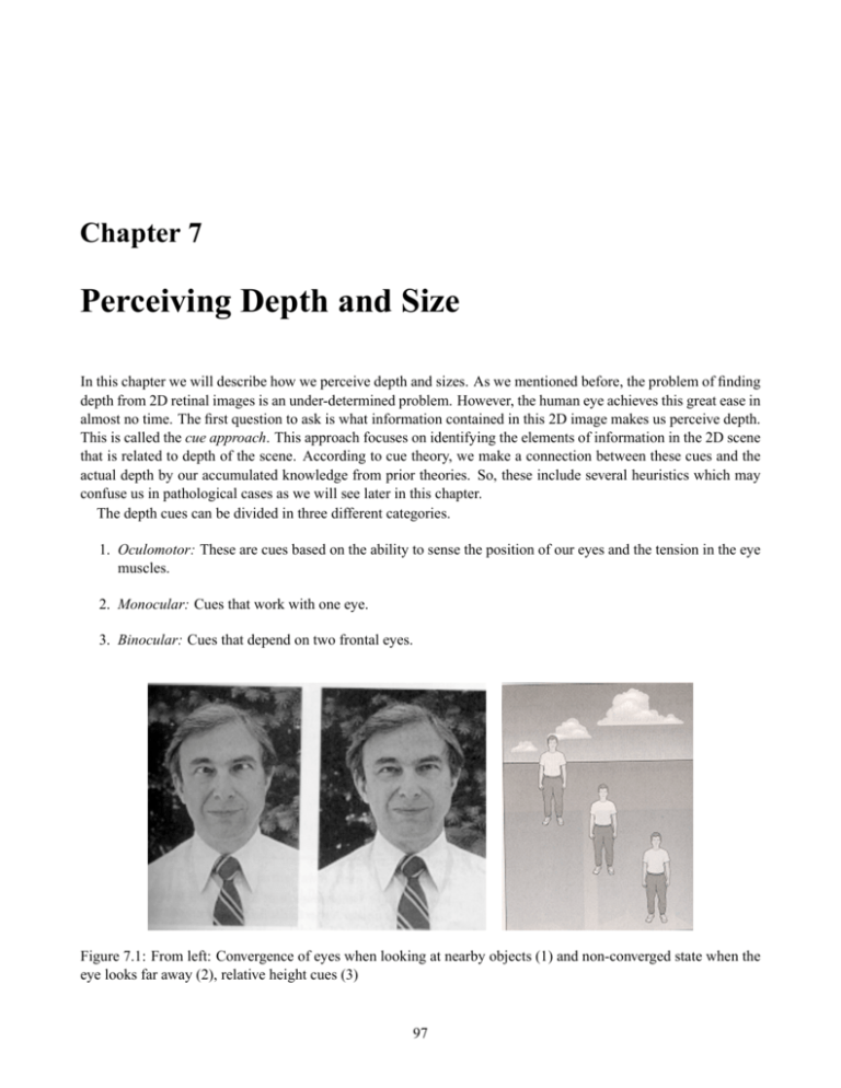
Chapter 7 Perceiving Depth and Size In this chapter we will describe how we perceive depth and sizes. As we mentioned before, the problem of finding depth from 2D retinal images is an under-determined problem. However, the human eye achieves this great ease in almost no time. The first question to ask is what information contained in this 2D image makes us perceive depth. This is called the cue approach. This approach focuses on identifying the elements of information in the 2D scene that is related to depth of the scene. According to cue theory, we make a connection between these cues and the actual depth by our accumulated knowledge from prior theories. So, these include several heuristics which may confuse us in pathological cases as we will see later in this chapter. The depth cues can be divided in three different categories. 1. Oculomotor: These are cues based on the ability to sense the position of our eyes and the tension in the eye muscles. 2. Monocular: Cues that work with one eye. 3. Binocular: Cues that depend on two frontal eyes. Figure 7.1: From left: Convergence of eyes when looking at nearby objects (1) and non-converged state when the eye looks far away (2), relative height cues (3) 97 98 CHAPTER 7. PERCEIVING DEPTH AND SIZE 7.1 Oculomotor Cues Oculomotor cues are due to convergence and accommodation. When looking at nearby objects our eyes move inwards. This is called convergence. and when looking at far away objects, our eyes move outward, as shown in Figure 7.1. This associated with accommodation. When the eyes move inward there is a tightening of the muscles that hold the lens to to get the eye to focus close by. When the eye moves outward, muscles relax. We can sense both of these which gives us an estimate about the depth of the object. You can experience this by moving an object at your arm’s length closer and closer to the eye to feel the tightening of the muscles and then move it back again to feel the muscles relax. Figure 7.2: Left: Occlusion Cues, Middle: Contradicting Occlusion and Relative Height Cues, Right: Shadows resolving the contradiction. 7.2 Monocular Cues Figure 7.3: Left: Relative size cues. Right: Familiar size cues. Monocular cues are the ones that are obtained from the 2D image of only one eye. These include the following. 1. Occlusion: When one object is hidden fully or partially, this hidden (occluded) object is considered to be farther away, behind object which is covering it (occluding object). Figure 7.2 illustrates occlusion. 2. Relative Cues: The second cue is that of relative height. The objects that are farther away have higher bases in the image as shown in Figure 7.1. The three men in this figure are perceived at different depths and the 7.2. MONOCULAR CUES 99 man with feet higher up in the image appears farther away. However, note the perception is entirely different for the clouds. The clouds with highest base appears to be closest and they seem to be at greater depth as the height of their bases decrease. The objects which are above the horizon look closer if their bases are higher. 3. Shadows: Figure 7.2 shows as an example where the occlusion and the relative height cues contradict each other. In such cases, we depend on some other cues. Shadows provide very important depth cues. In this case, the presence of the shadow removes the contradiction by telling that the vase is in front of the glass but at a higher depth. 4. Relative Size: If two objects are equal in size, one that is farther away will take up less of the field of view than the closer one. This is called the relative size cue as illustrated in Figure 7.3. However, note that this depends on our ability of recognize different parts of the 2D image as similar objects. It may seem trivial, but object recognition from images is a difficult problem. 5. Familiar Size: Our knowledge of sizes of objects can affect our perception. This is called the cues of familiar size. For example, our familiarity with the sizes of the different types of coins is important in perceive the depth of the array of dimes and quarters in Figure 7.3. Under conducive lighting conditions, people perceived the dime to be closer than the quarter and the quarter to be closer than the half dollar. Figure 7.4: Left: Atmospheric Perspective Cues. Right: Linear Perspective and Texture gradient cues. 6. Atmospheric Perspective: Atmospheric perspective makes us see distant objects as blurred as shown in Figure 7.4. We look at objects through atmosphere which has suspended dust and water particles in the air. Light from distant objects needs to traverse more such particles. Thus very little light from those objects reach our eye and we can perceive high frequencies with so less light. So, we tend to see distant objects as blurred. 7. Linear Perspective and Texture Gradient: Parallel lines in the environment that are not parallel to the retinal image plane do not remain parallel in the 2D image. With depth the distance between such lines become smaller and smaller and they seem to vanish at infinity. This is the basis of projective geometry. This linear perspective helps us give depth cues. Texture surface in particular show such a gradient due to linear perspective that provides additional cues about the depth of scenes, as shown in Figure 7.4. 8. Movement Produced Cues: So far, we have considered only stationary images. However, our eyes are constantly moving. Also, our head movements allow us to change our viewpoints of the environment very 100 CHAPTER 7. PERCEIVING DEPTH AND SIZE frequently. These movements cause motion parallax by which nearby objects tend to cross the retinal image plane faster than the distant objects which serve as an important depth cue. This is the same phenomenon that makes nearby objects from a train speedily pass by in a blur, but distant objects move slightly. This is illustrated in Figure 7.5. When the eye moves to the right, the nearby point A moves from A1 to A2 . The distance moved by the faraway point B, given by B1 to B2 is much smaller. This also lead to deletion and accretion of objects as shown in Figure 7.5. As we move, parts of objects gets revealed or occluded. The rate of these deletion and accretion provide information about the depth of the objects. One important point to note here is that monocular cues do not provide absolute information about depth, but relative depth with respect to other objects in the environment. Figure 7.5: Left: Motion Parallex. Right: Motion parallax causing deletion and accretion of objects. 7.3 Binocular Cues Figure 7.6: Images from two different eyes. Though they look similar, closer look will reveal the differences. For example, notice the difference in distance between the helmet of the man in foreground from the man over his shoulder in the two images. Binocular cues depend on the images from both the eyes. Our eyes are placed about 6cm apart and hence they 7.3. BINOCULAR CUES 101 get a different view of the objects in the environment that appear in both the eyes. Since we have frontal eyes, the overlap of the view from two eyes is significant but the viewpoint is different. This difference is called binocular disparity and is converted to depth information. The information provided by the disparity is called stereopsis. The image of the same scene from the different viewpoints of the two eyes are shown in Figure 7.6. This revelation lead to design of several systems where depth perception can be generated. Such displays were called stereo displays. One popular approach was taken in cinema projection where differently polarized light was used to project the images from two different viewpoints on the same screen. The users were provided with glasses. The left glass allowed one direction of polarization and the right glass allowed the other. Thus, though the users were watching the same screen, two eyes received two different images. The right image was blocked by the left glass and vice versa. This created a compelling sense of depth. Similar technologies were used in head-mounted displays where a head gear with two micro-screens, one in front of each eye, is mounted on the head of the user. The images of scenes are generated from two different viewpoints and projected on the two different screens to create a compelling sense of depth. 7.3.1 Binocular Disparity Figure 7.7: Left:Corresponding Points. Right: Different cues working together to create a vivid sensation of depth. Figure 7.8: Left: The horopter. Middle: Points on the horopter are imaged at corresponding points of the two eyes. Right: The depth of the points not on the horopter can be estimated by their disparity. Now, we will see what exactly is binocular disparity. Corresponding retinal points are the locations in each retina which connect to the same place in the visual cortex. We can determine these points by locating the matching 102 CHAPTER 7. PERCEIVING DEPTH AND SIZE points on the retina when one retina could be slid on top of another. Figure 7.7 shows the corresponding points A and A0 , B and B 0 , and F and F 0 . When we fixate at a point F shown in Figure 7.8, all the points lying on the circle defined by F and the focii of the two eyes, are imaged at corresponding points in the two eyes. This circle is called the horopter. In this example, we show the eye of a lifeguard who is watching a bunch of kinds in the swimming pool. Ralph, Harry and Susan are on his horopter and hence their images are at corresponding points of the two eyes. Now, let us take the case of Charlie and Carol who are closer than the horopter. Note that the images of these points closer than the horopter do not lie on corresponding points across the retina. For example, Carol’s image on the left eye and right eye are at B and G0 respectively. The angle between B and corresponding point G (with focus as center) in left eye is same as the angle between B 0 and G0 in right eye. This angle defines the disparity of a point. Note that as the distance to an object within the horopter increases the images move away near the sides from the image of the horopter. However, if the objects are beyond the horopter, as the distance increases, the images move towards the inner part of the eye. This information, in addition to disparity, helps us to decide whether the object is within the horopter or beyond it. There are physiological evidence that we are sensitive to this kind of disparity. Cells have been identified in the visual cortex that respond selectively to different ranges of disparities. There are also evidence of cells that fire when objects beyond the horopter are imaged and other which fire when objects within the horopter are imaged. These together corroborates the fact that we do perceive depth with the aid of disparity. However, one important point to note here is that, to find the disparity we need to find the two non-corresponding points on the retinal image where the same point has been imaged. For example, from the retinal images, we should somehow figure out that G0 in right eye is the image of the same point that is imaged at B in the left eye. This is called the correspondence problem. Though we humans do it with utter ease, this stage is a very difficult stage for computer vision algorithms. Now that we have described all the different cues that we use to perceive depth, lets see how these work together to create a vivid sensation of depth. Figure 7.7 illustrates that. Note that we use occlusion and relative size cues at al depths, but disparity and motion cues are only used at closer depths. Also, relative height and atmospheric perspective are used only for distant objects. Another important point to note is that disparity can only be used by animals who have frontal eyes like cats, dogs, humans etc. For example, a rabbit has lateral eyes (on both sides of the head) and hence cannot use disparity to sense depth. However, they have a wider view of the world than animals with frontal eyes. These kinds of animals have much better ways of using movement cues to sense the depth. By evolution, it has been sees that predators like humans, canines etc have frontal eyes since depth perception is extremely important for them to hunt successfully. However animals lower in the food chain, herbivores like rabbit and deers usually have lateral eye to get a larger field of view so that they are aware of a larger part of the environment and sense predators better. 7.4 Perception of Size Our perception of size depends closely on our perception of depth. If the size of an object in retinal image be R, the depth of object be D and the focal length of eye, the perceived size S is related to these by the similar triangle equation S D DR = ; S= (7.1) R F F This was also demonstrated by an very effective experiment. The experiment set up and results are shown in Figure 7.9. A person was positioned at the junction of two hallways. A comparison pattern was in front of him. On his right was a test circle. The size of the test circle was increased proportionately with its depth, as per Equation 7.1, so that the size of the retinal image remains same. Then he was asked to change the size of comparison circle to match the size of the test circle he perceives. Note that the size of the test circle in the retina remained same the 7.5. VISUAL ILLUSIONS 103 Figure 7.9: Left: The Experimental SetUp. Right: User response with changing depth and size of the test. size was changed with depth to keep the retinal image same. The right image of Figure 7.9 plots the perceived size of the test circle with its distance from the viewer. The slanted dashed line shows the actual change in size of the test circle, and the horizontal dashed line shows the size of the retinal image which is constant. Line 1 shows the subjects perception when all the depth cues were present. This shows that though the retinal size is same, the user can make use of depth cues to perceive a size that is close to reality. Line 2 shows the results when one of the subject’s eyes was closed, i.e. when binocular cue was absent. Note that the accuracy reduces. Line 3 shows the perceived size when the subject was looking through a peephole so that all monocular cues are absent. Line 4 shows the response when the walls were covered with drapes so that there are no shading cues. This illustrates that as the number of depth cues reduces our perception of size starts to fail and reaches closer to the retinal size. Another important aspect of size perception is by using relative size. For example, if we see a photo of a canyon, it is difficult to see how big it is. As soon as we put a human in the photo, we can easily perceive its size. This is because we know the size of a human and this knowledge helps us to perceive the size of the canyon. 7.5 Visual Illusions Size perception affects our veridical experience and works well in well-lighted natural environments. However, if conditions are adverse, some pathological cases can be designed where our size perception can falter. In this section, we introduce some such visual illusions. Figure 7.10: Left: The 2D Muller-Lyer Illusion. Right: Inside and outside corner explanation of Muller-Lyer Illusion 104 CHAPTER 7. PERCEIVING DEPTH AND SIZE The left image of Figure 7.10 shows one example. Note that the vertical line of the left figure looks shorter than that of the right figure though if you measure them with scale they are the same. The right image Figure 7.10 is one possible explanation. These two lines represent to us an outside and inside corner respectively. Since the depth of the inside corner is more, we tend to perceive the line as longer, following Equation 7.1. Figure 7.11: Left: The 3D Muller-Lyer Illusion. Right: Another Muller-Lyer Illusion. Figure 7.12: Left: The 3D Muller-Lyer Illusion. Right: Another Muller-Lyer Illusion. However, note that this explanation cannot explain the 3D Muller-Lyer illusion (Figure 7.11) that can be easily constructed by a couple of books. Here even though these are not perceived as corner, we perceive the space between the left one to be smaller than the right one, though when measured they are the same. The second explanation that seems more plausible is that of conflicting cues. This says that our perception of the length of the lines depend not only on the actual length of the figures but also on the overall length of the figure. If the overall length of the figure is more, we tend to perceive the line as longer. This is further strengthened by another example of this illusion in Figure 7.11. The distance between the two points in the right image are same for both the (a) and (b). But we perceive one as longer than the other. Figure 7.12 shows the Ponzo illusion. Though the two white lines have same size, the one at the top appears longer. This is explained by the fact that the perspective projection provides us with a strong cue for depth which tells us the upper line is further away than the bottom one. Hence, we perceive a longer line, as per Equation 7.1. The second illusion in Figure 7.12 is that of Ames room. Note how the two people look so different in size. Actually they are similar in height. The Ames room was designed as shown in the right image of Figure 7.12 so that one corner had a high wall and another corner has lower walls. From a particular angle of the camera, the image of this room can be such that two people seem to differ in height immensely. Our relative size cue aggravates the situation. We expect walls to be high. When one person’s head is close to ceiling, she appears taller than the other whose head is far down from the ceiling. 7.5. VISUAL ILLUSIONS 105 The final illusion is the moon illusion. Many of us may have noted that the moon appears much larger in the horizon than in the sky. One possible reason for this is when we look high is the empty sky, there is almost no depth cue to help us perceive the size of the moon. However, when it is closer to horizon, more depth cues are present giving us a perception of its size.
