Student Protocol using Chart 5.4.2 for Windows.
Respiratory Airflow and Volume
In this laboratory, you will be introduced to spirometry as a technique for recording respiratory variables and
you will analyze a recording to derive respiratory parameters. You will examine lung volumes and capacities,
as well as the basic tests of pulmonary function and simulate an airway restriction.
Written by staff of ADInstruments.
Background
Gas exchange between air and blood occurs in the alveolar air sacs. The efficiency of gas exchange is
dependent on ventilation; cyclical breathing movements alternately inflate and deflate the alveolar air sacs
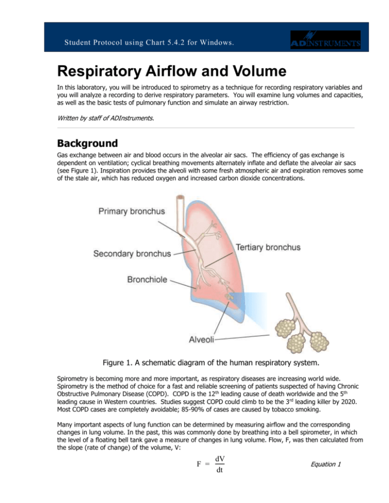
(see Figure 1). Inspiration provides the alveoli with some fresh atmospheric air and expiration removes some
of the stale air, which has reduced oxygen and increased carbon dioxide concentrations.
Figure 1. A schematic diagram of the human respiratory system.
Spirometry is becoming more and more important, as respiratory diseases are increasing world wide.
Spirometry is the method of choice for a fast and reliable screening of patients suspected of having Chronic
Obstructive Pulmonary Disease (COPD). COPD is the 12th leading cause of death worldwide and the 5th
leading cause in Western countries. Studies suggest COPD could climb to be the 3 rd leading killer by 2020.
Most COPD cases are completely avoidable; 85-90% of cases are caused by tobacco smoking.
Many important aspects of lung function can be determined by measuring airflow and the corresponding
changes in lung volume. In the past, this was commonly done by breathing into a bell spirometer, in which
the level of a floating bell tank gave a measure of changes in lung volume. Flow, F, was then calculated from
the slope (rate of change) of the volume, V:
F =
dV
dt
Equation 1
Student Protocol
More conveniently, airflow can be measured directly with a pneumotachometer (from Greek roots meaning
“breath speed measuring device”). The PowerLab pneumotachometer arrangement is shown in Figure 2.
Figure 2. The PowerLab pneumotachometer.
Several types of flow measuring devices are available and each type has advantages and disadvantages. The
flow head you will use today is a “Lilly” type that measures the difference in pressure either side of a mesh
membrane with known resistance. This resistance gives rise to a small pressure difference proportional to
flow rate. Two small plastic tubes transmit this pressure difference to the Spirometer Pod, where a
transducer converts the pressure signal into a changing voltage that is recorded by the PowerLab and
displayed in LabTutor. The volume, V, is then calculated as the integral of flow:
V=
F dt
Equation 2
This integration represents a summation over time; the volume traces that you will see in LabTutor during
the experiment are obtained by adding successive sampled values of the flow signal and scaling the sum
appropriately. The integral is initialized to zero every time a recording is started.
A complication in the volume measurement is caused by the difference in air temperature between the
Spirometer Pod (at ambient temperature) and the air exhaled from the lungs (at body temperature). The
volume of gas expands with warming, therefore the air volume expired from the lungs will be slightly greater
than that inspired. Thus a volume trace, as calculated by integration of flow, drifts in the expiratory
direction. To reduce the drift, the flow has to be integrated separately during inspiration and expiration, with
the inspiratory volume being corrected by a factor related to the BTPS factor (body temperature, atmospheric
pressure, saturated with water vapor). The LabTutor software makes this correction.
Spirometry allows many components of pulmonary function (see Figure 3 below) to be visualized, measured
and calculated. Respiration consists of repeated cycles of inspiration followed by expiration. During the
respiratory cycle, a specific volume of air is drawn into and then expired from the lungs; this volume is the
Tidal Volume (VT). In normal ventilation, the breathing frequency (ƒ) is approximately 15 respiratory cycles
per minute. This value varies with the level of activity. The product of ƒ and V T is the Expired Minute Volume
(VE), the amount of air exhaled in one minute of breathing. This parameter also changes according to the
SPB14e
Page 2 of 17
8 March 2016
Student Protocol
level of activity. Note that the volume of air remaining in the lungs after a full expiration, residual volume
(RV), cannot be measured by spirometry as a volunteer is unable to exhale any further.
Figure 3. Lung volumes and capacities.
Terms that you should be familiar with before coming to class.
Term
Abbreviation / Symbol
Respiratory Rate
Expired Minute Volume
Units
RR
VE RRxVT
breaths / min (BPM)
L/min
VT
IRV
ERV
RV (predicted)
L
L
L
L
IC = VT + IRV
EC = VT + ERV
VC = IRV + ERV + VT
FRC = ERV + RV
TLC = VC + RV
L
L
L
L
L
PIF
PEF
FVC
FEV1
FEV1/FVC x 100
L/min
L/min
L
L
Lung Volumes
Tidal Volume
Inspiratory Reserve Volume
Expiratory Reserve Volume
Residual Volume
Lung Capacities
Inspiratory Capacity
Expiratory Capacity
Vital Capacity
Functional Residual Capacity
Total Lung Capacity
Pulmonary function tests
Peak Inspiratory Flow
Peak Expiratory Flow
Forced Vital Capacity
Forced Expired Volume in one second
% FVC expired in one second
SPB14e
Page 3 of 17
8 March 2016
Student Protocol
What you will do in the laboratory
There are five exercises that you will complete during this Lab.
1. Becoming familiar with the equipment. In this exercise, you will learn the
principles of spirometry, and how integration of the flow signal gives a volume.
2. Lung volumes and capacities. Here you will examine the respiratory cycle and
measure changes in flow and volume.
3. Pulmonary function tests. Here you will measure parameters of forced expiration
that are used in evaluating pulmonary function.
4. Simulating an airway restriction. In this exercise, you will simulate an airway
restriction.
5. Variability amongst group members. In this exercise, you will compare the
parameters of forced expiration measured in different students.
Required Equipment
A computer system
Chart for Windows, version 5.4.2 or later
Spirometry extension 2.0 for Chart 5
PowerLab 4/25T or other Chart 5 compatible PowerLab.
Spirometer Pod or Spirometer amp
Respiratory flow head (1000 L/min) with connection tubes
Clean bore tubing
Disposable filters
Disposable vinyl mouthpieces
Nose clip
Tape measure or wall chart for measuring height
Vital capacity prediction tables
Procedures
Set up and calibration of equipment
A. Connecting the equipment
Connect the Spirometer Pod to the Pod Port for Input 1 on the PowerLab.
Since the Spirometer Pod is sensitive to temperature and tends to drift during warm-up, we recommend that
the PowerLab and Spirometer Pod be turned on for at least 5-10 minutes before use. To prevent
temperature drift, place the Spirometer Pod on a shelf or beside the PowerLab, away from the PowerLab
power supply to avoid heating.
SPB14e
Page 4 of 17
8 March 2016
Student Protocol
Connect the two plastic tubes from the respiratory flow head to the short pipes on the back of the
Spirometer Pod, as shown in Figure 2
Attach clean bore tubing, a filter and mouthpiece to the flow head.
Figure 2. Setting up the spirometry experiment: connecting the flow head and attachments to the Spirometer
Pod. The cable from the back of the Spirometer Pod to the Pod Port for Input 1 on the front of the
PowerLab is not shown in this figure.
B. Hygiene
NOTE: A clean mouthpiece and air filter should be supplied for each volunteer. The vinyl mouthpiece can
be cleaned between uses by soaking it in boiling water or a suitable disinfectant. If you are suffering from a
respiratory infection, we suggest that you do not volunteer for this experiment.
C. Starting the software
1. Locate Chart on your computer and start the software.
2. In the Experiments Gallery dialog box, select “Respiratory” from the left-hand list. Select “Respiratory
Settings” from the right-hand list, and click the Open button to apply those settings. If the Experiments
Gallery dialog box does not appear in front of the Chart View, choose the Experiments Gallery…
command from the File menu.
3. After a short time, the Chart View on the computer screen should be set up for the experiment. Channels
1 and 2 are visible, with Channel 2 turned off; Channel 1 is named “Flow” and Channel 2 “Volume”.
D. Calibrating the Spirometer Pod
4. The flow head must be left undisturbed on the bench during the zeroing process.
SPB14e
Page 5 of 17
8 March 2016
Student Protocol
5. Choose Spirometer… from the Flow Channel
Function pop-up menu. The Spirometer Pod
dialog box appears, as shown in Figure 3.
Click the Zero button.
6. When zeroing has finished, have the volunteer
breathe out gently through the flow head, and
note the recorded signal in the data display
area (Figures 3). If the signal shows a
downward deflection (that is, negative),
proceed to Step 9.
7. If the signal deflects upward, you need to
invert it. Click the Invert checkbox once to
toggle its state.
8. Click OK to close the dialog box and return to
the Chart View.
9. You are now ready to begin the exercises.
Figure 3. Spirometer Pod dialog box showing an exhaled breath
Note: the signal can also be inverted by reversing the orientation of the flow head, or by swapping the
tubular connections to the Spirometer Pod. The Invert checkbox is simply more convenient.
Exercise 1: Becoming familiar with the equipment
Objectives
In this exercise, you will learn the principles of spirometry, and how integration of the flow signal gives a
volume.
Procedure
1. The volunteer should put the mouthpiece in his or her mouth, and hold the flow head carefully with both
hands. The two plastic tubes should be pointing upwards.
2. Put the nose clip on the volunteer’s nose. This ensures that all air breathed passes through the
mouthpiece, filter and flow head (Figure 4).
3. After the volunteer becomes accustomed to the apparatus and begins breathing normally, you are ready
to begin.
4. Click the Start button to begin recording.
5. Have the volunteer perform a full expiration and then breathe normally. Record the volunteer’s tidal
breathing for one minute. At the end of one minute, have the volunteer perform another full expiration.
You should observe data being recorded in the Flow channel, but not in the Volume channel.
6. Click Stop to end the recording. The volunteer can stop breathing through the flow head and remove the
nose clip.
SPB14e
Page 6 of 17
8 March 2016
Student Protocol
Figure 4. The volunteer should hold the flow head as shown here.
Setting up the Spirometry Extension
The Spirometry Extension processes the raw voltage signal from the Spirometer Pod, applies a volume
correction factor to improve accuracy, and displays calibrated Flow (L/s) and Volume (L) traces. It takes over
from units conversion. The trace that you recorded in this exercise will provide reference points for the
Spirometry Extension that allow it to calculate and perform corrections on the trace.
Select the data you just recorded by clicking and dragging
along the time scale at the bottom of the chart window.
1. Choose Spirometry Flow… from the Flow (Channel
1) Channel Function pop-up menu. The Spirometry
Flow dialog box appears (Figure 5).
Flow (Channel 1) should be selected in the Flow Data popup menu; MLT 1000L should be selected in the Flow Head
Calibration pop-up menu. When you are finished and the
settings are the same as in Figure 5, click the OK button to
close the dialog box.
Do not check the Drift Correction box unless instructed to
specifically by your instructor
Figure 5 Spirometry flow dialog
SPB14e
Page 7 of 17
8 March 2016
Student Protocol
Choose Spirometry Volume… from the Volume
(Channel 2) Channel Function pop-up menu. The
Spirometry Volume dialog box appears (Figure
6).
Flow (Channel 1) should be selected in the
Spirometry Flow Data pop-up menu. Ensure that
Volume Correction is on. Click the Apply button
to allow the extension to use the volume
correction ratio that it has calculated from your
data.
When you are finished, click the OK button to
close the dialog box. The Chart View should now
appear with calculated volume data on Channel
2.
Figure 6. The Spirometry Volume dialog box.
Choose Set Scale… from the Scale pop-up menu in the Amplitude axis for the Flow channel. Make the top
value 15 L/s and the bottom value –15 L/s, and click OK.
2. Choose Set Scale… from the Scale pop-up menu in the Amplitude axis for the Volume channel. Make
the top value 5 L and the bottom value –5 L, and click OK.
Analysis 1: Becoming familiar with the equipment
When examining the data, use the scroll buttons as necessary to view parts of the trace that have scrolled
out of sight.
Drag in the Time axis to select data from both channels and open the Zoom View. Note the relation between
Flow and Volume. When the flow signal is positive (inspiration), the Volume trace rises; when the flow is
negative (expiration), the Volume trace falls.
In the Zoom View, find a part of the recording where the flow is zero. Note that at this time the Volume
trace does not change (it is horizontal) because integrating a zero signal does not add anything to the
integral.
The volume trace is calculated by the extension in such a way that the displayed volumes at the end of the
two full expirations equal. In subsequent recordings, the volume correction is unlikely to be exact: you will
notice a tendency for the volume to drift, typically by 1–2 L over 1–2 minutes. To see the effect of having no
correction, turn off the Volume Correction checkbox in the Spirometry Volume dialog box (Figure 6), and
examine the volume trace. Remember to turn Volume Correction back on again afterwards.
SPB14e
Page 8 of 17
8 March 2016
Student Protocol
Exercise 2: Lung volumes and capacities
Objectives
In this exercise, you will examine the respiratory cycle and measure changes in flow and volume.
Procedure
NOTE: It is important when recording normal respiration that the volunteer is not consciously controlling
breathing. The volunteer should turn away from the computer screen and may have to stare out a window or
read a book to distract themselves.
1. The flow head must be left undisturbed on the bench during the zeroing process.
2. Choose the Spirometer Pod… item from the Flow channel Function pop-up menu. Click the Zero
button to re-zero the Spirometer Pod. When zeroing has finished, click the OK button to return to the
Chart View.
3. Click Start; Once recording has started ask the volunteer to replace the nose clip and breathe normally
through the flow head. Record normal tidal breathing for 1 to 2 minutes. Add the comment “Normal
tidal breathing” to the Chart trace.
4. After the tidal breathing period and at the end of a normal tidal expiration, ask the volunteer to inhale as
deeply as possible and then exhale as deeply as possible. Afterwards, allow the volunteer to return to
normal tidal breathing for at least 3 breaths, then stop recording.
5. Enter a comment called “Lung volume procedure” at the end of this deep breath (press Ctrl+K to open
the comment dialog).
Analysis 2: Lung volumes and capacities
6. Examine the normal tidal breathing data. Calculate how many breaths there are in a one-minute period
(bpm). Record RR/min in the table provided in your Data Notebook.
7. Determine the volume of a single tidal inspiration by dragging the Marker from its box to the Volume
channel at the start of a normal tidal inspiration. Move the Waveform Cursor to the next peak on the
Volume channel (this should be 0.5 to 1.5 s to the right of the Marker). Read off the numerical value of
Volume from the Range/Amplitude display at the right.
8. The number in the Range/Amplitude display should have a “∆” symbol in front of it, indicating that it is
the difference between the volume at the Waveform Cursor position and the volume at the Marker
position. If you have both the Marker and the pointer in the right places, the value shown is the Tidal
Volume (VT) for that breath. Record this value in the table in your Data Notebook. See figure 7.
9. Return the Marker to its box at bottom left of the Chart View, by double-clicking the Marker, dragging
it back, or clicking its box.
10. Using the value for VT and the number of breaths, (RR/min), observed over a one-minute period,
Ý ) using Equation 3. Record your value in the table.
calculate the Minute Volume ( V
E
Ý = RR x V
V
E
T
(L/min)
Equation 3
SPB14e
Page 9 of 17
8 March 2016
Student Protocol
Figure 7. A typical tidal breathing record, displayed at 20:1 horizontal compression. The Marker and
Waveform Cursor are positioned to measure the Tidal Volume of a single breath.
11. Find the “Lung volume procedure” comment in your data trace. Repeat steps 2-3 to determine the
Inspiratory Reserve Volume (IRV) (Fig. 8) and Expiratory Reserve Volume (ERV) (Fig. 9). Note, the
Marker should remain at the start of a normal tidal inspiration (trough) for the ERV, and it should be
moved to the end of a normal tidal inspiration (peak) for for the IRV.
Figure 8. Record of full inhalation, with the Marker and Waveform Cursor positioned to measure IRV.
SPB14e
Page 10 of 17
8 March 2016
Student Protocol
Figure 9. Record of full exhalation, with the Marker and Waveform Cursor positioned to measure ERV.
12. Calculate the Inspiratory Capacity (IC) using Equation 4.
IC = VT + IRV
(L)
Equation 4
13. Calculate the Expiratory Capacity (EC) using Equation 5.
EC = VT + ERV
(L)
Equation 5
14. Use the table provided to determine the volunteer’s predicted Vital Capacity (VC). The predicted value
varies according to the volunteer’s sex, height and age.
15. Calculate the volunteer’s measured VC using the experimentally derived values for IRV, ERV and VT
(Equation 6).
VC = IRV + ERV + VT
(L)
Equation 6
16. Residual Volume (RV) is the volume of gas remaining in the lungs after a maximal expiration. The RV
cannot be determined by spirometric recording. Using Equation 7, determine the predicted RV value for
the volunteer. This equation predicts RV for 16–34 year-old subjects of either sex (Gaensler and Wright,
1966).
RV = predicted VC X 0.25
(L)
Equation 7
17. The Total Lung Capacity (TLC) is the sum of the vital capacity and residual volume. Calculate the
predicted TLC for the volunteer (Equation 8) using the predicted values for VC and RV.
TLC = VC + RV
SPB14e
(L)
Page 11 of 17
Equation 8
8 March 2016
Student Protocol
18. Functional Residual Capacity (FRC) is the volume of gas remaining in the lungs at the end of a normal
tidal expiration (the sum of the RV and ERV). Calculate the FRC value for the volunteer using Equation
9.
FRC = ERV + RV
(L)
Equation 9
19. Select an area of the Chart View that contains normal breathing, making sure to select across complete
respiratory cycles. Choose the Report command from the Spirometry menu. The Spirometry Report
window contains various parameters calculated by the Spirometry Extension from the data selection
Ý , VT and ƒ into the table in your Data Notebook.
(Figure 10). Copy the results for V
E
Figure 10. The Spirometry Report window, listing the parameters calculated from the data selection.
Exercise 3: Pulmonary function tests
Objectives
In this exercise, you will measure parameters of forced expiration that are used in evaluating pulmonary
function. Note that the Spirometry Extension is not intended for clinical evaluation of lung function.
Procedure
1. Re-zero the flow head using steps 1-2 from the procedures in Exercise 2.
2. Click the Start button to begin recording.
SPB14e
Page 12 of 17
8 March 2016
Student Protocol
3. Prepare a comment called “Forced Breathing’’.
4. Have the volunteer breathe normally for 30 seconds.
5. Ask the volunteer to inhale maximally and then exhale as forcefully and fully as possible (that is, inhale
as much as possible and then exhale until no more air can be expired). Press the Enter key to add the
comment. After a few seconds, the volunteer should let his or her breathing return to normal.
6. Click Stop to end recording.
7. Repeat steps 2–6 twice more, so that you have three separate forced breath recordings. Your recording
should resemble Figure 11.
Peak inspiratory flow
Peak expiratory flow
FVC
Figure 11. A spirometry recording showing where to find PIF and PEF, and how to determine FVC.
Analysis 3: Pulmonary function test
In the last data block of your Chart recording, move the Waveform Cursor to the maximal forced
inspiration on the Flow trace. The absolute value displayed in the Range/Amplitude display is the Peak
Inspiratory Flow (PIF). Multiply the value by 60 to convert from L/s to L/min.
8. From the Flow trace, measure the Peak Expiratory Flow (PEF) for the forced expiration. Multiply the
value by 60 to convert from L/s to L/min. (Disregard the negative sign.)
SPB14e
Page 13 of 17
8 March 2016
Student Protocol
9. To calculate the Forced Vital Capacity (FVC), place the Marker on the peak inhalation of the Volume
trace and move the Waveform Cursor to the maximal expiration (Figure 12). Read off the result from
the Range/Amplitude display. (Disregard the delta symbol and the negative sign.)
10. Return the Marker to its box at bottom left, by double-clicking the Marker, dragging it back, or clicking
its box.
11. To measure Forced Expired Volume in 1 second (FEV1), place the Marker on the peak of the Volume
trace, move the pointer to a time 1.0 s from the peak, and read off the volume value. If you find it hard
to adjust the mouse position with enough precision, a time value anywhere from 0.96 to 1.04 s gives
enough accuracy. (Disregard the delta symbol and the negative sign.)
12. Return the Marker to its box at bottom left, by double-clicking the Marker, dragging it back, or clicking
the box.
13. Make a selection from the last recorded data block that includes a couple of normal breaths, the forced
breath, then a few more normal breaths (Figure 12). Choose Spirometry Data from the Spirometry
menu. The Spirometry Data window opens, showing the locations of PIF, PEF, FVC and FEV1 (Figure 12).
If the values aren’t displayed, check that you have included a forced breath in your selection. If your
selection is correct but the parameters are still not displayed, you should ask for assistance.
The Spirometry
extension
marks forced
breaths with a
grey area.
Vertical lines
mark half
breath cycles
(inspiration and
expiration)
Figure 12. The Spirometry Data window, with the locations of the forced expiration parameters indicated.
14. Open the Spirometry Report window. The report lists the values calculated for those parameters. Add
the report values to your Data Notebook table.
15. Repeat the analysis until all three forced breaths have been analyzed, both manually and with the
Spirometry Extension.
SPB14e
Page 14 of 17
8 March 2016
Student Protocol
16. Calculate the percentage ratio of FEV1 to FVC for your experimental and Spirometry Extension results
using Equation 10. Use the maximum values of FEV 1 and FVC.
(FEV1/FVC) / 100
(%)
Equation 10
Exercise 4: Forced expiration in different volunteers
Objectives
In this exercise, you will compare the parameters of forced expiration measured in different volunteers.
Procedure
1. Replace the disposable filter and mouthpiece.
2. Re-zero the Spirometer Pod; follow the procedures in steps 1-2 from Exercise 2.
3. Repeat the procedures in Exercise 3 for the new volunteer.
4. Repeat steps 1–3 until the forced expiration parameters (PIF, PEF, FVC and FEV1) have been measured
for all volunteers.
Analysis 4: Forced expiration in different volunteers
5. Repeat the analysis procedures from Exercise 3 on the recordings from each volunteer. Have each
member of your group record their data in their own Data Notebook. Give a copy of your data to each
member of your group.
Exercise 5 Simulating airway restrictions
You can demonstrate the effects of bronchial restrictions such as asthma by making the following
modification to your equipment.
1. Remove the filter attachment from the mouthpiece and clean-bore tubing.
2. Attach a new filter to the clean bore tubing.
3. Cover the other end of the mouthpiece with duct tape.
4. Use a sharpened pencil to make a hole in the duct tape over the filter one centimeter in diameter.
5. Place the mouthpiece on the filter.
6. Attempt the pulmonary function tests with the restricted airway.
Analysis 5: Simulating airway restrictions
7. Repeat the analysis procedures from Exercise 3 on the recordings from each volunteer. Have each
member of your group record their data in their own Data Notebook. Give a copy of your data to each
member of your group.
SPB14e
Page 15 of 17
8 March 2016
Student Protocol
Data Notebook
Table 1. Respiratory parameters
Respiratory parameter
Respiratory Rate
Abbreviation
RR
Units
breaths/min
(BPM)
VE RRxVT
L/min
VT
L
Inspiratory Reserve
Volume
IRV
L
Inspiratory Capacity
IC= VT + IRV
L
Expiratory Reserve
Volume
ERV
L
Expiratory Capacity
EC= VT + ERV
L
VC (from table)
VC = IRV + ERV +
VT
RV = pred. VC x
0.25
L
Total Lung Capacity
TLC = VC + RV
L
Functional Residual
Capacity
FRC = ERV + RV
L
PIF
L/min
Expired Minute Volume
Tidal Volume
Vital Capacity
Residual Volume
Peak Inspiratory Flow
Experimental &
calculated value
Spirometry
Extension value
L
L
L/min
L/min
Peak Expiratory Flow
PEF
L/min
L/min
L/min
Forced Vital Capacity
FVC
L
L
L
Forced Expired Volume
in one second
FEV1
L
L
L
FEV1/FVC x 100
SPB14e
L
Page 16 of 17
8 March 2016
Student Protocol
Study Questions
1. Comment on the differences between the experimental and predicted values for VC, FRC and TLC in the
table above. What could cause these differences, if any?
2. In quiet breathing, muscular effort is used mainly in inspiration, and expiration is largely passive, due to
elastic recoil of the lung. Can you relate this fact to the pattern of expiratory and inspiratory flow? Hint:
the normal pattern of breathing is efficient in that it requires muscular effort for only a short time.
3. Explain why RV cannot be determined by ordinary spirometry?
4. What factors do you think could contribute to differences in pulmonary parameters between the
menmbers of your group/class?
5. Based on your data, what values have been affected by simulated airway restriction and why?
6. In your own words explain the physiological events that occurred during this simulated asthma attack.
Hint: Think about what it felt like and how that would affect your general state of well being and activity
level.
References
Gaensler, E.A., and G.W. Wright. 1966. Evaluation of respiratory impairment. Archives of Environmental Health 12:146–
189.
Copyright © 2006 ADInstruments. All rights reserved.
MacLab and PowerLab are registered trademarks, and Chart and Scope are trademarks, of ADInstruments. Windows and the
Windows logo are either trademarks or registered trademarks of Microsoft Corporation. Macintosh and the Mac logo are either
trademarks or registered trademarks of Apple Computer, Inc. Other trademarks are the properties of their respective owners.
www.ADInstruments.com
SPB14e
Page 17 of 17
8 March 2016


