The register set_PPAPAG
advertisement
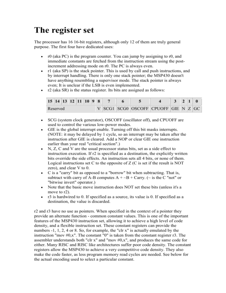
The register set The processor has 16 16-bit registers, although only 12 of them are truly general purpose. The first four have dedicated uses: r0 (aka PC) is the program counter. You can jump by assigning to r0, and immediate constants are fetched from the instruction stream using the postincrement addressing mode on r0. The PC is always even. r1 (aka SP) is the stack pointer. This is used by call and push instructions, and by interrupt handling. There is only one stack pointer; the MSP430 doesn't have anything resembling a supervisor mode. The stack pointer is always even; It is unclear if the LSB is even implemented. r2 (aka SR) is the status register. Its bits are assigned as follows: 15 14 13 12 11 10 9 8 Reserved 7 6 5 4 3 2 1 0 V SCG1 SCG0 OSCOFF CPUOFF GIE N Z GC SCG (system clock generator), OSCOFF (oscillator off), and CPUOFF are used to control the various low-power modes. GIE is the global interrupt enable. Turning off this bit masks interrupts. (NOTE: it may be delayed by 1 cycle, so an interrupt may be taken after the instruction after GIE is cleared. Add a NOP or clear GIE one instruction earlier than your real "critical section".) N, Z, C and V are the usual processor status bits, set as a side effect to instruction execution. If r2 is specified as a destination, the explicitly written bits override the side effects. An instruction sets all 4 bits, or none of them. Logical instructions set C to the opposite of Z (C is set if the result is NOT zero), and clear V to 0. C is a "carry" bit as opposed to a "borrow" bit when subtracting. That is, subtract with carry of A-B computes A + ~B + Carry. (~ is the C "not" or "bitwise invert" operator.) Note that the basic move instruction does NOT set these bits (unless it's a move to r2). r3 is hardwired to 0. If specified as a source, its value is 0. If specified as a destination, the value is discarded. r2 and r3 have no use as pointers. When specified in the context of a pointer they provide an alternate function - common constant values. This is one of the important features of the MSP430 instruction set, allowing it to achieve a high level of code density, and a flexible instruction set. These constant registers can provide the numbers -1, 1, 2, 4 or 8. So, for example, the "clr x" is actually emulated by the instruction "mov #0,x". The constant "0" is taken from the constant register r3. The assembler understands both "clr x" and "mov #0,x", and produces the same code for either. Many RISC and RISC like architectures suffer poor code density. The constant registers allow the MSP430 to achieve a very competitive code density. They also make the code faster, as less program memory read cycles are needed. See below for the actual encoding used to select a particular constant. Note that some assemblers for the MSP430 allow the use of the alternate names "PC" for "r0", "SP" for "r1", and "SR" for "r2". GNU msp430 binutils does not understand these alternate names. You must use "r0", "r1" or "r2".
