THEVENIN'S THEOREM Aim: To verify Thevenin's theorem
advertisement

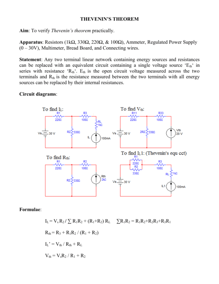
THEVENIN’S THEOREM Aim: To verify Thevenin’s theorem practically. Apparatus: Resistors (1kΩ, 330Ω, 220Ω, & 100Ω), Ammeter, Regulated Power Supply (0 – 30V), Multimeter, Bread Board, and Connecting wires. Statement: Any two terminal linear network containing energy sources and resistances can be replaced with an equivalent circuit containing a single voltage source ‘E th‘ in series with resistance ‘Rth‘. Eth is the open circuit voltage measured across the two terminals and Rth is the resistance measured between the two terminals with all energy sources can be replaced by their internal resistances. Circuit diagrams: Formulae: IL = Vs R2 / ∑ R1R2 + (R1+R2) RL Rth = R3 + R1R2 / (R1 + R2) IL’ = Vth / Rth + RL Vth = VsR2 / R1 + R2 ∑R1R2 = R1R2+R2R3+R3R1 Tabular forms: Table – 1: S.No Vs (volts) Vth (volts) Theoretical Practical Vs (volts) IL’(mA) Theoretical Practical IL(mA) Theoretical Practical Table – 2: S.No Procedure: Step-1: Connect the circuit as shown in the fig: Step-2: By varying the voltage source Vs and set to the voltage. Step-3: Measure IL in the load resistor RL and tabulate the readings in table-1. Step-4: Repeat the steps 2 & 3 for different values of Vs. Step-5: Connect the next circuit as shown in fig: Step-6: Set the voltage Vs and measure the voltage Vth by the voltmeter and tabulate reading in table-1. Step-7: Repeat the step-6 for different values of Vs. Step-8: Connect the next circuit as shown in fig: Step-9: Measure the value of Rth using Ohm-meter. Step-10: Connect the next circuit as shown in fig: Step-11: Set the Vth to a value such that the voltage of Vs and measure the IL and tabulate the reading in table-2. Step-12: Repeat the step-11 for different values of Vth. Precautions: 1. Connect the circuit as shown fig: perfectly’ 2. Loose connections are avoided. 3. Shot circuits are avoided. 4. While measuring voltages and currents the range of the Multimeter should be altered. Result: Hence the Thevenin’s theorem verified practically. NORTON’S THEOREM Aim: To verify Norton’s theorem practically. Apparatus: Resistors (100kΩ, 1kΩ, 330Ω, 220Ω, & 100Ω), Ammeter, Regulated Power Supply (0 – 30V), Multimeter, Bread Board, and Connecting wires. Statement: Any two terminal linear network containing energy sources and resistances can be replaced with an equivalent circuit containing a single current ‘IN’ in parallel with a resistance ‘RN‘. IN is the shot circuit current and RN is the resistance measured between the two terminals with all energy sources can be replaced by their internal resistances. Circuit diagrams: Formulae: IL = Vs R2 / ∑ R1R2 + (R1+R2) RL RN = R3 + R1R2 / (R1 + R2) IL’ = IN RN / RN + RL IN = Vs R2 / R1R2+R2R3+R3R1 ∑R1R2 = R1R2+R2R3+R3R1 Tabular forms: Table-1: S.No Vs (volts) IN (mA) Theoretical Practical IL(mA) Theoretical Practical Table-2: S.No IN (mA) ILl(mA) Theoretical Practical Procedure: Step-1: Connect the circuit as shown in the fig: Step-2: By varying the voltage source Vs and set to the voltage. Step-3: Measure IL in the load resistor RL and tabulate the readings in table-1. Step-4: Repeat the steps 2 & 3 for different values of Vs. Step-5: Connect the next circuit as shown in fig: Step-6: Set the voltage Vs and measure the current in the ammeter IN and tabulate reading in table-1. Step-7: Repeat the step-6 for different values of Vs. Step-8: Connect the next circuit as shown in fig: Step-9: Measure the value of RN using Ohm-meter. Step-10: Connect the next circuit as shown in fig: Step-11: Set the IN to a value such that the voltage of Vs and measure the IL and tabulate the reading in table-2. Step-12: Repeat the step-11 for different values of IN. Precautions: 1. Connect the circuit as shown fig: perfectly’ 2. Loose connections are avoided. 3. Shot circuits are avoided. 4. While measuring voltages and currents the range of the Multimeter should be altered. Result: Hence the Norton’s theorem verified practically. MAXIMUM POWER TRANSFER THEOREM Aim: To verify Maximum power transfer theorem practically. Apparatus: Resistors (470Ω, 220Ω, & 100Ω), Variable resistance box, Regulated Power Supply (0 – 30V), Multimeter, Bread Board, and Connecting wires. Statement: A load will receive maximum power from a linear bilateral dc network when its total resistance value is exactly equal to the thevenin’s resistance of the network as seen by the load RL = Rth. Circuit diagram: Model graph: PLl Power PL (mwatts) RLl Load resistance (RL) Ω Formula: RTh = R3 + R1 R2 / (R1 + R2) S.No Load Resistance RL Ω Voltage Across ( RL ) VL ( volts ) PL = VL2/RL (mw)


