wedsa
advertisement
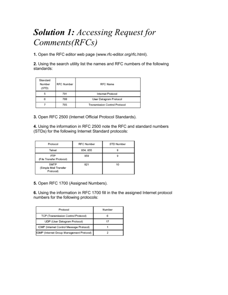
Solution 1: Accessing Request for Comments(RFCs) 1. Open the RFC editor web page (www.rfc-editor.org/rfc.html). 2. Using the search utility list the names and RFC numbers of the following standards: 3. Open RFC 2500 (Internet Official Protocol Standards). 4. Using the information in RFC 2500 note the RFC and standard numbers (STDs) for the following Internet Standard protocols: 5. Open RFC 1700 (Assigned Numbers). 6. Using the information in RFC 1700 fill in the the assigned Internet protocol numbers for the following protocols: 7. Using the information in RFC 1700 fill in the well known port numbers for the following protocols: 8. Open RFC 1812, what RFCs does it make obsolete? 9. What is RFC 1878? Solution 2: Changing and Testing IP Configuration Part 1 All ping tests fail except for the loop-back address and the PC's own address. In all other cases the PC will determine that the destination IP address is on a remote IP network. Therefore the PC will attempt to contact its default gateway, which does not exist. Part 2 The ping tests to all remote IP addresses including the far side of the router fail, because the PC's default gateway is incorrectly configured. Part 3 No ping test fails, provided all PC's are now correctly configured Part 4 All Ping tests except the one to the local PC will fail. All other devices including the default gateway are in a different subnet because of the subnet mask. The IP address of the PC's must be changed to become part of the subnet defined by the routers. Subnet 1 Router 192.168.10.33 255.255.255.224 Valid IP addresses for PCs anything between 192.168.10.34 and 192.168.10.62 Subnet 2 Router 192.168.30.33 255.255.255.224 Valid IP addresses for PCs anything between 192.168.30.34 and 192.168.30.62 Solution 3: Subnetting and CIDR Part 1 Assume that you have been assigned the 132.45.0.0/16 network block. You need to establish eight equal-sized subnets. 1. 3 binary digits are required to define eight subnets. 2. Specify the extended-network-prefix that allows the creation of 8 subnets. /19 or 255.255.224.0 3. Express the subnets in binary format and dotted decimal notation: Subnet #0: 10000100.00101101. 000 00000.00000000 = 132.45.0.0/19 Subnet #1: 10000100.00101101. 001 00000.00000000 = 132.45.32.0/19 Subnet #2: 10000100.00101101. 010 00000.00000000 = 132.45.64.0/19 Subnet #3: 10000100.00101101. 011 00000.00000000 = 132.45.96.0/19 Subnet #4: 10000100.00101101. 100 00000.00000000 = 132.45.128.0/19 Subnet #5: 10000100.00101101. 101 00000.00000000 = 132.45.160.0/19 Subnet #6: 10000100.00101101. 110 00000.00000000 = 132.45.192.0/19 Subnet #7: 10000100.00101101. 111 00000.00000000 = 132.45.224.0/19 4. List the range of host addresses that can be assigned to Subnet #3 (132.45.96.0/19). Subnet #3: 10000100.00101101.011 00000.00000000 = 132.45.96.0/19 Host #1: 10000100.00101101.011 00000.00000001 = 132.45.96.1/19 Host #2: 10000100.00101101.011 00000.00000010 = 132.45.96.2/19 Host #3: 10000100.00101101.011 00000.00000011 = 132.45.96.3/19 ::::::::::: Host #8190: 10000100.00101101.011 11111.11111110 = 132.45.127.254/19 5. What is the broadcast address for Subnet #3 (132.45.96.0/19)? 10000100.00101101.011 11111.11111111 = 132.45.127.255/19 Part 2 Assume that you have been assigned the 200.35.1.0/24 network block. 1. Define an extended-network-prefix that allows the creation of 20 hosts on each subnet. A minimum of five bits are required to define 20 hosts so the extended-networkprefix is a /27 (27 = 32-5). 2. What is the maximum number of hosts that can be assigned to each subnet? The maximum number of hosts on each subnet is 25 -2, or 30. 3. What is the maximum number of subnets that can be defined? The maximum number of subnets is 23 or 8. 4. Specify the subnets of 200.35.1.0/24 in binary format and dotted decimal notation. Subnet #0: 11001000.00100011.00000001. 000 00000 = 200.35.1.0/27 Subnet #1: 11001000.00100011.00000001. 001 00000 = 200.35.1.32/27 Subnet #2: 11001000.00100011.00000001. 010 00000 = 200.35.1.64/27 Subnet #3: 11001000.00100011.00000001. 011 00000 = 200.35.1.96/27 Subnet #4: 11001000.00100011.00000001. 100 00000 = 200.35.1.128/27 Subnet #5: 11001000.00100011.00000001. 101 00000 = 200.35.1.160/27 Subnet #6: 11001000.00100011.00000001. 110 00000 = 200.35.1.192/27 Subnet #7: 11001000.00100011.00000001. 111 00000 = 200.35.1.224/27 5. List range of host addresses that can be assigned to Subnet #6 (200.35.1.192/27). Subnet #6: 11001000.00100011.00000001. 110 00000 = 200.35.1.192/27 Host #1: 11001000.00100011.00000001.110 00001 = 200.35.1.193/27 Host #2: 11001000.00100011.00000001.110 00010 = 200.35.1.194/27 Host #3: 11001000.00100011.00000001.110 00011 = 200.35.1.195/27 :::::::::::: Host #29: 11001000.00100011.00000001.110 11101 = 200.35.1.221/27 Host #30: 11001000.00100011.00000001.110 11110 = 200.35.1.222/27 6. What is the broadcast address for subnet 200.35.1.192/27? 11001000.00100011.00000001.110 11111 = 200.35.1.223 Part 3 - CIDR Exercise 1. List the individual /24 networks numbers defined by the CIDR block 200.56.168.0/21. Step 1 Express the CIDR block in binary format: 200.56.168.0/21 11001000.00111000.10101 000.00000000 Step 2 The /21 mask is 3 bits shorter than the natural mask for a traditional /24. This means that the CIDR block identifies a block of 8 (or 23) consecutive /24 network numbers. Step 3 The range of /24 network numbers defined by the CIDR block 200.56.168.0/21 includes: Net #0: 11001000.00111000.10101000 .xxxxxxxx 200.56.168.0 Net #1: 11001000.00111000.10101001 .xxxxxxxx 200.56.169.0 Net #2: 11001000.00111000.10101010 .xxxxxxxx 200.56.170.0 Net #3: 11001000.00111000.10101011 .xxxxxxxx 200.56.171.0 Net #4: 11001000.00111000.10101100 .xxxxxxxx 200.56.172.0 Net #5: 11001000.00111000.10101101 .xxxxxxxx 200.56.173.0 Net #6: 11001000.00111000.10101110 .xxxxxxxx 200.56.174.0 Net #7: 11001000.00111000.10101111 .xxxxxxxx 200.56.175.0 2. List the individual /24 networks numbers defined by the CIDR block 195.24/13. Step 1 Express the CIDR block in binary format: 195.24.0.0/13 11000011.00011 000.00000000.00000000 Step 2 The /13 mask is 11 bits shorter than the natural mask for a traditional /24. This means that the CIDR block identifies a block of 2,048 (or 211) consecutive /24 network numbers. Step 3 The range of /24 network numbers defined by the CIDR block 195.24/13 include: Net #0: 11000011.00011000.00000000 .xxxxxxxx 195.24.0.0 Net #1: 11000011.00011000.00000001 .xxxxxxxx 195.24.1.0 Net #2: 11000011.00011000.00000010 .xxxxxxxx 195.24.2.0 ::::::::: Net #2045: 11000011.00011111.11111101 .xxxxxxxx 195.31.253.0 Net #2046: 11000011.00011111.11111110 .xxxxxxxx 195.31.254.0 Net #2047: 11000011.00011111.11111111 .xxxxxxxx 195.31.255.0 3. Aggregate the following set of (4) IP /24 network addresses to the highest degree possible. 212.56.132.0/24 212.56.133.0/24 212.56.134.0/24 212.56.135.0/24 Step 1 List each address in binary format and determine the common prefix for all of the addresses: 212.56.132.0/24 11010100.00111000.10000100 .00000000 212.56.133.0/24 11010100.00111000.10000101 .00000000 212.56.134.0/24 11010100.00111000.10000110 .00000000 212.56.135.0/24 11010100.00111000.10000111 .00000000 Common Prefix: 11010100.00111000.100001 00.00000000 Step 2 The CIDR aggregation is: 212.56.132.0/22 4. Aggregate the following set of (4) IP /24 network addresses to the highest degree possible. 212.56.146.0/24 212.56.147.0/24 212.56.148.0/24 212.56.149.0/24 Step 1 List each address in binary format and determine the common prefix for all of the addresses: 212.56.146.0/24 11010100.00111000.10010010 .00000000 212.56.147.0/24 11010100.00111000.10010011 .00000000 212.56.148.0/24 11010100.00111000.10010100 .00000000 212.56.149.0/24 11010100.00111000.10010101 .00000000 Step 2 Note that this set of four /24s cannot be summarized as a single /23! 212.56.146.0/23 11010100.00111000.1001001 0.00000000 212.56.148.0/23 11010100.00111000.1001010 0.00000000 Step 3 The CIDR aggregation is: 212.56.146.0/23 212.56.148.0/23 Note that if two /23s are to be aggregated into a /22, then both /23s must fall within a single /22 block! Since each of the two /23s is a member of a different / 22 block, they cannot be aggregated into a single /22 (even though they are consecutive!). They could be aggregated into 222.56.144/21, but this aggregation would include four network numbers that were not part of the original allocation. Hence, the smallest possible aggregate is two /23s. 5. Aggregate the following set of (64) IP /24 network addresses to the highest degree possible. 202.1.96.0/24 202.1.97.0/24 202.1.98.0/24 :::::: 202.1.126.0/24 202.1.127.0/24 202.1.128.0/24 202.1.129.0/24 ::::::: 202.1.158.0/24 202.1.159.0/24 Step 1 List each address in binary format and determine the common prefix for all of the addresses: 202.1.96.0/24 11001010.00000001.01100000 .00000000 202.1.97.0/24 11001010.00000001.01100001 .00000000 202.1.98.0/24 11001010.00000001.01100010 .00000000 ::::::: 202.1.126.0/24 11001010.00000001.01111110 .00000000 202.1.127.0/24 11001010.00000001.01111111 .00000000 202.1.128.0/24 11001010.00000001.10000000 .00000000 202.1.129.0/24 11001010.00000001.10000001 .00000000 ::::::: 202.1.158.0/24 11001010.00000001.10011110 .00000000 202.1.159.0/24 11001010.00000001.10011111 .00000000 Step 2 Note that this set of 64 /24s cannot be summarized as a single /19! 202.1.96.0/19 11001010.00000001.011 00000.00000000 202.1.128.0/19 11001010.00000001.100 00000.00000000 Step 3 The CIDR aggregation is: 202.1.96.0/19 202.1.128.0/19 Similar to the previous example, if two /19s are to be aggregated into a /18, the /19s must fall within a single /18 block! Since each of these two /19s is a member of a different /18 block, they cannot be aggregated into a single /18. They could be aggregated into 202.1/16, but this aggregation would include 192 network numbers that were not part of the original allocation. Thus, the smallest possible aggregate is two /19s. Solution 4: Variable Length Subnet Masking Background A company is allocated the IP addresses space 200.100.152.0/22. Without further subnetting, this gives 1 network, with a maximum of 1,022 devices. This is unsuitable for the company's requirements, which are as follows: One "central" site with 200 hosts. Four "large" remote sites, two with 50 hosts and two with 40 hosts each. Four "small" remote sites, two with 25 hosts and two with 20 hosts each. All eight remote sites are linked to the central site across WAN links, with separate routers at both ends. Central Site Subnet mask of 255.255.255.0 (/24) 1 X 254 host network 200.100.152.0 Large Remote Sites Subnet mask of 255.255.255.192 (/26) 4 X 62 host networks 200.100.153.0 200.100.153.64 200.100.153.128 200.100.153.192 Small Remote Sites Subnet mask of 255.255.255.224 (/27) 8 X 30 host networks 200.100.154.0 200.100.154.32 200.100.154.64 200.100.154.96 200.100.154.128 200.100.154.160 200.100.154.192 200.100.154.224 WAN Links Subnet mask of 255.255.255.252 (/30) 64 X 2 host networks 200.100.155.0 200.100.155.4 200.100.155.8 200.100.155.12 200.100.155.16 200.100.155.20 200.100.155.24 etc….. Note: All IP addresses on the following diagram start with 200.100. Solution 5: Viewing and Modifying the ARP Cache 1. View the PC's ARP cache using arp -a command. The ARP cache is empty if the PC has not communicated recently (in the last two minutes) with any other device. 2. Ping the other PC on the same LAN and view the ARP cache. 3. Note the type of entry. Dynamic 4. Note this entry times out after two minutes. 5. When the ARP cache is empty, do a continuous ping to the other PC on the same LAN (ping -t address). 6. Open a second DOS screen and confirm that the ARP entry does not clear. 7. End the continuous ping. 8. Ping the IP address of the Ethernet interface of the local router. 9. View the ARP cache and take a note of the hardware address of the router. 10. Put a permanent entry into the ARP cache for the router ( arp -s 192.168.x.1 hardware address). Note it may be necessary to ping the router first for this command to take effect. 11. What is the entry type? Static (permanent) 12. Reboot the PC. 13. Check the ARP cache. Is it empty? The ARP cache empties on reboot. 14. Ping the local PC. What IP and hardware addresses are in the ARP cache? 15. Ping the two remote PCs. What IP and hardware addresses are in the ARP cache and why? When you ping a remote device the IP software knows that this IP packet must be delivered to the local router (default gateway). Therefore your PC will send an ARP broadcast to find the Ethernet address of the local router, not the remote device. 16. Put in a wrong hardware address for the router in the ARP cache. 17. Check the ARP table. 18. Ping a remote PC. Does it work, why or why not ? No, it does not work because the PC is using the wrong Ethernet address for the local router (default gateway). 19. Ping the local PC. Does it work, why or why not? Yes, it does work because the default gateway is irrelevant in this case. 20. Remove the wrong entry from the ARP cache (arp -d 192.168.x.x). 21. Ping remote PC. Does it work, why or why not? Yes, it does work, because the PC will send an ARP broadcast and get back the correct Ethernet address for the local router (default gateway). Solution 6: Sniffer Trace Background The attached is a trace of ten ethernet frames generated by 2 different devices on a LAN segment: 1. Fill in the information in the table below: 2. What is contained inside all of the IP packets (protocol name and number)? ICMP, number 1 3. What command did the PC user type, to generate packets (3,5,7 and 9)? ping 192.168.10.1 4. Why did the PC generate frame 1 and under what circumstances would it not do this? The PC did not know the Ethernet address that corresponded to the IP address 192.168.10.1. If the PC did know the Ethernet address, in other words it was contained in the PC's ARP table. Solution 7: Opening a Connection - TCP Three-way Handshake 1. Fill in the gaps below (sequence numbers and acknowledgement numbers). 2. The server's window size is 3000 bytes. 3. Assume the diagram below represents the same TCP connection between the client and server later on. Fill in the gaps below (sequence numbers and acknowledgement numbers). 4. At the time marked X below, why can the client not send the next 1,000 byte segment? The client can only send a maximum of 3,000 bytes to the server without receiving any acknowledgements. Otherwise it would exceed the server's window size. 5. What will happen when the timeout period expires on the client? The client will retransmit the packet which was lost (sequence number 35,500 and acknowledgement number 4,100). The server will store the segments which were out of sequence until the missing segment is received. Finally, the server will resequence the segments. The server will acknowledge all segments received as shown in the diagram below. 6. Assume the diagram below represents the same TCP connection between the client and server later on and that the timeout period has just expired. Fill in the gaps below (sequence numbers and acknowledgement numbers). Solution 8: TCP/IP The following pages contain a trace of Ethernet frames between a PC and a router. Frame 1 Frame 1 is the first frame from the PC to the router. Questions 1. What are the source and destination port numbers? Source port = 1040 Destination port = 23 2. Why did the PC use these particular source and destination port numbers? The PC is initiating a Telnet session. It must use the "well-known" port number 23 so that the router recognises the connection as Telnet. It can randomly generate the source port number. 3. Why is the TCP data offset 24 bytes? Options are used to specify maximum segment size. 4. What is a more common size for the TCP data offset field? 20 bytes 5. What is the purpose of this TCP segment? Connection establishment, the first part of the three-way handshake. 6. What is the window size in bytes? 8,192 bytes 7. What is the maximum segment size? 1,456 bytes 8. Why is there a sequence number but no acknowledgement number in this segment? The PC generates it's own starting sequence number. The PC has not yet received any segments from the Router; therefore it has nothing to acknowledge. Frame 2 Frame 2 is from the router to the PC. Questions 1. What is the purpose of this TCP segment? Acknowledgement and synchronisation. The second part of the three-way handshake. 2. What is the maximum segment size? 1,024 bytes 3. What is the window size? 4,096 bytes 4. How many maximum size segments can the PC send without receiving an acknowledgement? Four (4,096 divide by 1,024) Note: In practice, this is not only limited by the advertised window size, but also by the congestion window size. Frame 3 Frame 3 is from the PC to the router. Questions 1. Why is the data offset 20 bytes? No options. Note all the subsequent segments are also 20 bytes. 2. What is the purpose of this TCP segment? Acknowledgement, the third part of the three-way handshake. Frame 4 - Frame 12 Frame 4 to Frame 12 are part of a telnet session between the PC and the router. 1. Which frame numbers contain Telnet information? 4, 5, 6, 7, 9, 10, 12 2. Frame number 4 contains three Telnet commands from the router to the PC. IAC Will Suppress go-ahead IAC Will Status IAC Will Echo IAC means Interpret As Command. "Will" is a negotiation request for a characteristic that the router wants to enable for it's side of the Telnet session. The response from the PC is either "do" for accept or "don't" for reject. In what frames does the PC reply to these three commands? Which requests are accepted? In Frame 5 the PC accepts go-ahead "Telnet: IAC Do Suppress go-ahead" In Frame 7 the PC rejects status, but accepts Echo "Telnet: IAC Don't Status Telnet: IAC Do Echo" 3. In which frame number does the router request the login? Six 4. What are the first two letters of the login? n (frame 9) e (frame 12) 5. Why is the telnet data in frame 10 the same as the Telnet data in frame 9? Frame ten is an echo from the router to the PC, so that the user can see what they are typing on the screen. 6. If frame 11 contains no Telnet information why was it sent? What is the difference in the TCP flags field between frame 11 and frame 12? Frame 11 was sent by the PC as a TCP acknowledgement to frame 10. Frame 11 has the PUSH bit set as well as the ACK bit; therefore it contains actual data. (1 byte of data the letter "e"). 1. Fill in the acknowledgement and sequence numbers in the table above. 2. What is the difference between sequence number of frame 3 and the sequence number of frame 1 and why? The SYN bit is set in frame 1; therefore TCP counts the segment as one data byte and increments the sequence number by one. 3. What is the difference between sequence number of frame 9 and the sequence number of frame 7 and why? Frame 7 contains 6 bytes of data therefore the sequence number of frame 9 is incremented by six. 4. What is the difference between sequence number of frame 11 and the sequence number of frame 12 and why? There is no difference, because frame 11 does not contain any data. 5. Assuming frame 13 is from the router to the PC to acknowledge receipt of frame 12, fill in the following information: TCP: Source port = 23 (Telnet) TCP: Destination port = 1040 TCP: Sequence number = 2,160,499,827 TCP: Acknowledgement number = 5,251,368 Solution 9: DHCP The attached is a trace of four Ethernet frames, which contain DHCP messages, generated by 2 different devices on a LAN segment: 1. Fill in the information in the table below: 2. What transport layer protocol is used to transport the DHCP message? UDP 3. What are the source and destination ports of frame 1? Source port 68 Bootpc/DHCP (Bootp Client) Destination port 67 Bootps/DHCP (Bootp Server) 4. In frame 1 the client requests to use the specific IP address 192.168.30.100. In frame 3 the client requests to use the specific IP address 192.168.10.52. Why does the PC request these particular addresses and why are they different? The IP address 192.168.30.100 was a dynamic IP address assigned to the client by a different DHCP server on a different network. When the client boots up it request to use this address. In frame 2 The DHCP server offers the client the IP address 192.168.10.52, which is a valid address for the network the PC has now moved to. 5. How long is the lease time on the IP address which the DHCP server offers? 3,600 seconds (1 hour)
