Lab#07 - 2nd Semester Notes
advertisement
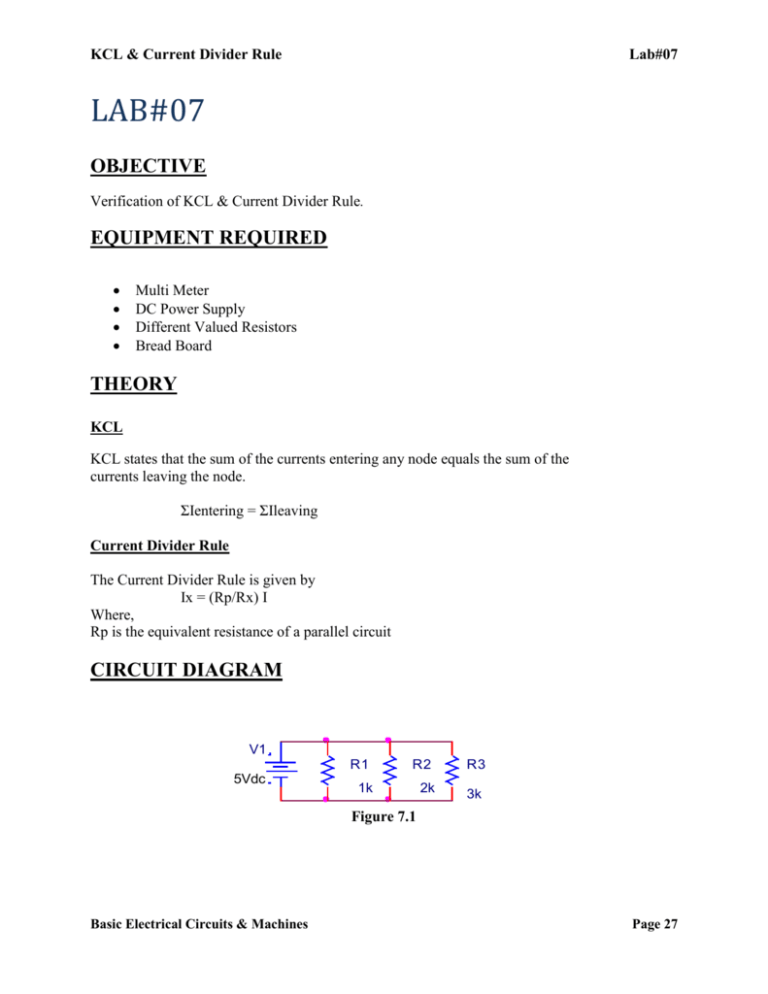
KCL & Current Divider Rule Lab#07 LAB#07 OBJECTIVE Verification of KCL & Current Divider Rule. EQUIPMENT REQUIRED Multi Meter DC Power Supply Different Valued Resistors Bread Board THEORY KCL KCL states that the sum of the currents entering any node equals the sum of the currents leaving the node. ΣIentering = ΣIleaving Current Divider Rule The Current Divider Rule is given by Ix = (Rp/Rx) I Where, Rp is the equivalent resistance of a parallel circuit CIRCUIT DIAGRAM V1 5Vdc R1 R2 R3 1k 2k 3k Figure 7.1 Basic Electrical Circuits & Machines Page 27 KCL & Current Divider Rule Lab#07 PROCEDURE Connect two resistors R1 and R2 in parallel to a DC power supply as shown in Figure 7.1. Set E = 10V from the trainer board. Take readings of I1, I2 and I using ammeters Verify KCL (i.e. I = I1 + I2). Find Rp using the equation Verify Current Divider Rule (i.e. I1 = (Rp/R1) I & I2 = (Rp/R2) I OBSERVATION TABLE 7.1 Nominal Value Measured Resistance R1 = R2 = R3 = MEASURED VALUES Current across R1 = _____________ Current across R2 = _____________ Current across R3 = _____________ Total Current = _________________ CALCULATED VALUES Current across R1 = _____________ Current across R2 = _____________ Current across R3 = _____________ Total Current = _________________ Basic Electrical Circuits & Machines Page 28 KCL & Current Divider Rule Lab#07 EXERCISE Q1) Determine the voltages registered by a voltmeter between the following points in this circuit: VA = __________ (Red lead on A, Black lead on ground) VB = __________(Red lead on B, Black lead on ground) VC = __________(Red lead on C, Black lead on ground) VD = __________(Red lead on D, Black lead on ground) Q2) Determine what a digital voltmeter would indicate if connected between the following points: Red lead on A and Black lead on ground = ______________ Red lead on B and Black lead on ground = ______________ Red lead on A and Black lead on B = ______________ Basic Electrical Circuits & Machines Page 29 KCL & Current Divider Rule Red lead on B and Black lead on A Lab#07 = ______________ Q3) What will happen to the current through R1 and R2 if resistor R3 destroy? __________________________________________________________________________ __________________________________________________________________________ __________________________________________________________________________ __________________________________________________________________________ Q4) We know that the voltage in a parallel circuit may be calculated with this formula: E = ITRT We also know that the current through any single resistor in a parallel circuit may be calculated with this formula: Combine these two formulae into one, in such a way that the E variable is eliminated, leaving only Ir expressed in terms of IT, RT, and R. __________________________________________________________________________ __________________________________________________________________________ __________________________________________________________________________ Basic Electrical Circuits & Machines Page 30

