Experiment NO.4 Divider Rules Aim of experiment
advertisement
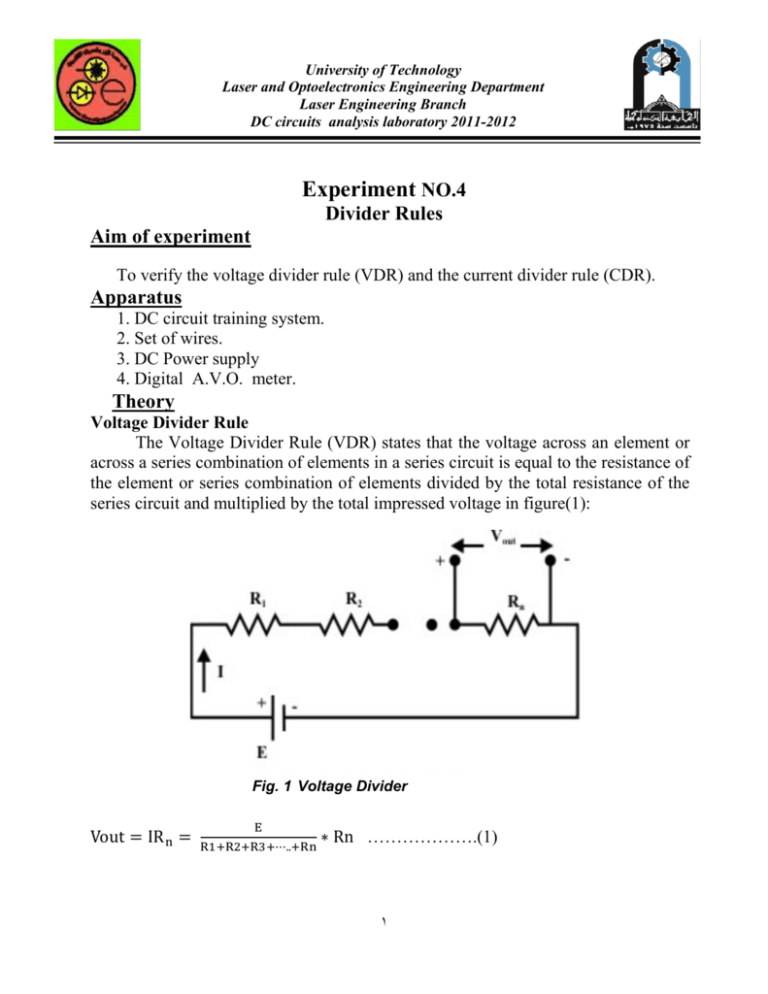
University of Technology Laser and Optoelectronics Engineering Department Laser Engineering Branch DC circuits analysis laboratory 2011-2012 Experiment NO.4 Divider Rules Aim of experiment To verify the voltage divider rule (VDR) and the current divider rule (CDR). Apparatus 1. DC circuit training system. 2. Set of wires. 3. DC Power supply 4. Digital A.V.O. meter. Theory Voltage Divider Rule The Voltage Divider Rule (VDR) states that the voltage across an element or across a series combination of elements in a series circuit is equal to the resistance of the element or series combination of elements divided by the total resistance of the series circuit and multiplied by the total impressed voltage in figure(1): Fig. 1 Voltage Divider ……………….(1) 1 University of Technology Laser and Optoelectronics Engineering Department Laser Engineering Branch DC circuits analysis laboratory 2011-2012 Indicates that the voltage across any resistor Ri(Ri, i= 1,2,..... n ) in a series circuit is equal to the applied voltage (E) across the circuit multiplied by a factor . It should be noted that this expression is only valid if the same current I flows through all the resistors. Current Divider Rule The Current Divider Rule (CDR) states that the current through one of two parallel branches is equal to the resistance of the other branch divided by the sum of the resistances of the two parallel branches and multiplied by the total current entering the two parallel branches in figure(2). That is, Fig. 2 Current Divider Or 2 University of Technology Laser and Optoelectronics Engineering Department Laser Engineering Branch DC circuits analysis laboratory 2011-2012 Similarly, the current flowing through the R2 can be obtained as: It can be noted that the expression for on its top line. has on its top line, that for has Procedure Part 1: Voltage Divider Rule 1. Using the DC circuit trainer, connect the circuit shown in Fig. (1), take E =10V, R1=82Ω, R2 = 100Ω and R3 =150Ω. 2. Measured the voltage and current of "R1 , R2 & R3". 3. Exchange the value of resistors as following: R1= 10KΩ, R2= 1000 Ω, R3= 50 Ω. 4. Repeat step(2) , change the value of resistors as following: R1=30 Ω, R2= 500 Ω, R3= 100 Ω. Part 2:Current Divider Rule 1. Using the DC circuit trainer, connect the circuit shown in Fig. (2). take E =10V, R1=82Ω and R2 = 100Ω . 2. Measured the voltage and current of "R1 , R2. 3. Exchange the value of resistors as following: R1= 10KΩ, R2= 1000 Ω. 4. Repeat step(2) , change the value of resistors as following: R1=30 Ω, R2= 500 Ω. Discussion 1- Comment on your results. 2- Compare between the practical and theoretical results. 3- When is used VDR and CDR. 4- For the circuit shown in Figure( 3 ) . Calculate V out, ignoring the internal resistance Rs of the source E. Use voltage division. 3 University of Technology Laser and Optoelectronics Engineering Department Laser Engineering Branch DC circuits analysis laboratory 2011-2012 Fig. 3 4 . Determine , , and using only current divider formula when 4 =4A.

