Test 1 Sample
advertisement
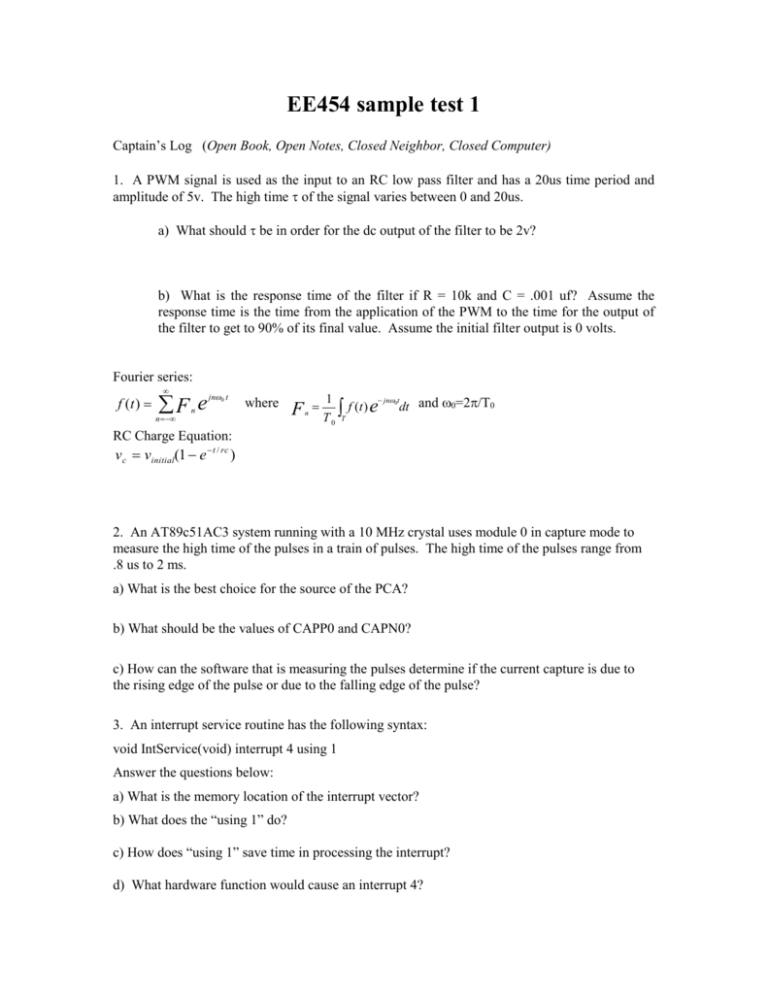
EE454 sample test 1
Captain’s Log (Open Book, Open Notes, Closed Neighbor, Closed Computer)
1. A PWM signal is used as the input to an RC low pass filter and has a 20us time period and
amplitude of 5v. The high time of the signal varies between 0 and 20us.
a) What should be in order for the dc output of the filter to be 2v?
b) What is the response time of the filter if R = 10k and C = .001 uf? Assume the
response time is the time from the application of the PWM to the time for the output of
the filter to get to 90% of its final value. Assume the initial filter output is 0 volts.
Fourier series:
f (t )
F e
n
jn 0 t
n
where
F
n
1
jn t
f (t ) e 0 dt and 0=2/T0
T
T0
RC Charge Equation:
vc vinitial(1 e t / rc )
2. An AT89c51AC3 system running with a 10 MHz crystal uses module 0 in capture mode to
measure the high time of the pulses in a train of pulses. The high time of the pulses range from
.8 us to 2 ms.
a) What is the best choice for the source of the PCA?
b) What should be the values of CAPP0 and CAPN0?
c) How can the software that is measuring the pulses determine if the current capture is due to
the rising edge of the pulse or due to the falling edge of the pulse?
3. An interrupt service routine has the following syntax:
void IntService(void) interrupt 4 using 1
Answer the questions below:
a) What is the memory location of the interrupt vector?
b) What does the “using 1” do?
c) How does “using 1” save time in processing the interrupt?
d) What hardware function would cause an interrupt 4?
4. Given the RL circuit to the right:
a) Write the differential equation that models the circuit.
b) Write the discrete time linear difference equation that can be used to simulate the circuit. If
you could not produce a differential equation for A) above use the equation:
d y(t )
dt
k x(t ) m y(t ) Where k and m are constants.
5. Given the initialize code below, answer the following:
a) How many interrupts are enabled and what are they?
b) Name the timers/counters that are being used and the mode they are in.
void Initialize()
{ TMOD = TMOD & 0xf0;
TMOD = TMOD | 0x01;
TH0 = -(20000 >> 8);
TL0 = -(20000);
IE = IE | 0x82;
TR0 = 1;
CMOD = 0X02;
CCAPM2 = 0X42;
CCON = 0X40;
IE = IE | 0x90; }
6. It is desired to input a 0 or a 1 into an AT89c51AC3. Sketch how you would connect a simple
normally open momentary push button switch to bit 0 of port 1. Write a module that will
return the single bit value of the state of the switch. The procedure should return a 1 if the
switch is pushed (closed) and a 0 if the switch is not pushed (open). Call the procedure
SwitchState(). Declare all variables used. An example of the possible use of SwitchState()
is shown below:
if (SwitchState()==1) then led = on;


![[Full Text]](http://s2.studylib.net/store/data/018641411_1-1c69a9db5dcfbe88b8d5dcedd9a40948-300x300.png)
