Chapter 11 Tolerancing
advertisement
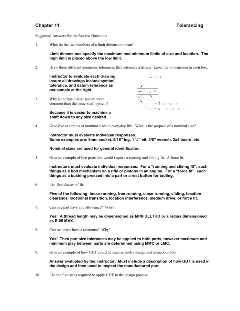
Chapter 11 Tolerancing Suggested Answers for the Review Questions 1. What do the two numbers of a limit dimension mean? Limit dimensions specify the maximum and minimum limits of size and location. The high limit is placed above the low limit. 2. Draw three different geometric tolerances that reference a datum. Label the information in each box. Instructor to evaluate each drawing. Insure all drawings include symbol, tolerance, and datum reference as per sample at the right. 3. Why is the basic-hole system more common than the basic-shaft system? Because it is easier to machine a shaft down to any size desired. 4. Give five examples of nominal sizes in everyday life. What is the purpose of a nominal size? Instructor must evaluate individual responses. Some examples are: 8mm socket, 5/16” lug, 1 ¼” bit, 3/8” wrench, 2x4 board, etc. Nominal sizes are used for general identification. 5. Give an example of two parts that would require a running and sliding fit. A force fit. Instructors must evaluate individual responses. For a “running and sliding fit”, such things as a bolt mechanism on a rifle or pistons in an engine. For a “force fit”, such things as a bushing pressed into a part or a rest button for tooling. 6. List five classes of fit. Five of the following: loose-running, free-running, close-running, sliding, location clearance, locational transition, location interference, medium drive, or force fit. 7. Can one part have any allowance? Why? Yes! A thread length may be dimensioned as MINFULLTHD or a radius dimensioned as R.05 MAX. 8. Can two parts have a tolerance? Why? Yes! Then part size tolerances may be applied to both parts, however maximum and minimum play between parts are determined using MMC or LMC. 9. Give an example of how GDT could be used as both a design and inspection tool. Answer evaluated by the instructor. Must include a description of how GDT is used in the design and then used to inspect the manufactured part. 10. List the five steps required to apply GDT to the design process. a. b. c. d. e. Define the part’s functions. List the functions by priority. Define the datum reference frame. Control selection. Calculate tolerances.
