LG Dynamic Braking Units
advertisement
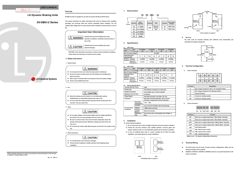
USER’S MANUAL 1. Overview LG Dynamic Braking Units SV-DBU-U Series Nomenclature Cooling fan SV DBU - 4U 150 SV-DBU-U series is designed to use with LG inverter SV-iS5 and SV-iH series. This manual describes the safety instructions that must be followed when installing, LG operating, and servicing. Read this manual completely before installing. The unit Drives Drive Capacity Symbol Symbol Type Symbol Drive Input Voltage Dynamic Braking Unit 2U 200V Class DBU 4U 400V Class contains high voltage that can cause electric shock resulting in personal injury or loss of life. Important User Information Indicates that incorrect handling may cause ! WARNING 150 11~15[kW] 220 18.5~22[kW] 370 30~37[kW] 550 45~55[kW] 750 75[kW] DB Unit or DB Resistor DB Unit or DB Resistor DB Unit or DB Resistor DB Unit or DB Resistor Air flow GOOD BAD <<Fan location in a panel>> hazardous conditions, resulting in personal injury or Mounting The units must be mounted vertically with sufficient room (horizontally and loss of life. 2. Specifications 2.1 200V Class vertically) from adjacent equipment. Indicates that incorrect handling may cause ! CAUTION physical damages. over 100mm Type SV150DBU -2U Spec. "CAUTION" level instructions may lead to a serious result according to conditions. Please follow the instructions of caution level for safety. Max. DC Input Voltage 1. Electric Shock 2.2 ! WARNING LG Industrial Systems 11 Spec. Be sure to remove all input power from the braking unit including drive Applicable Drive Capacity Braking Wattage Resistor Minimum Resistance Service only qualified personnel. ! CAUTION 37 45 6.4 [KW] 9.6 [KW] 4.2 [Ω] 2.8 [Ω] SV220DBU -4U SV370DBU -4U SV550DBU -4U 11 15 18.5 22 30 37 45 55 1) 6.4 [KW] 9.6 [KW] 12.8 [kW] 8.5 [Ω] 5.7 [Ω] 4.2 [Ω] 2.8 [Ω] 8.4 [Ω] Altitude may occur. Do not touch the resistor right after the power is turned off. The resistor is still hot. DC (+) input. Connect to “P2” or “P” terminal of drive Ground Terminal B1 Connect to braking resistor Heat Sink Overheat Protection, Over-Current Protection, Output Short Circuit Protection B2 Connect to braking resistor -10℃ ~ 40℃ 2) Control Terminals Less Than 90 % RH Max. (Non-Condensing) 1,000m above sea level Cooling Method Application Site Natural Convection IN+ No Corrosive Gas, Combustible Gas, Oil Mist, or Dust IN- OUT+ OUT- Terminal Installation 30B 30C 30A Function IN+ Slave turn on signal input (when “Slave Mode” selected) IN- Slave turn on signal input (when “Slave Mode” selected) OUT+ Slave turn on signal output (when “Master Mode” selected) 1) Do not mount the unit in direct sunlight. Isolate the unit from excessive vibration. OUT- Slave turn on signal output (when “Master Mode” selected) 2) Protect the unit from moisture, dust, metallic particles, corrosive gases and 30A Fault signal output Environmental Conditions liquids. Install the units on a non-flammable material and as smooth as possible. 30B 30A : Normal open contact 30B : Normal close contact 3) In case of installing many units in a panel, consider the air flows for power 4. Other Instructions Description P Heat Sink Overheat, Fuse Open, OC Trip Protection Operating Temperature Humidity B2 DC (-) input. Connect to “N” terminal of drive Installing them on a flammable material may cause a fire. Do not connect the braking resistor directly to the DC terminal (P2, N) of B1 N 6 seconds 3. G G Output Signal polarity of DC power terminal. Otherwise, damage and burst of the unit N Terminal 100% Mount the braking unit and resistor on a non-flammable material. Be sure to connect wires to the correct terminal. Especially, ensure the Power Terminals P the manual. This can cause damage and burst of the unit. Terminal Configuration 75 4.8 [KW] Connectable up to 3 units in parallel Do not apply voltage to the terminals higher than the voltage specified in SV750DBU -4U 3.2 [KW] 10% (without cooling fan on heat sink) ! CAUTION over100mm DC 800V Parallel Connection Environmental Conditions over 50mm 55 5.7 [Ω] Enable Duty the drive. This can cause a fire. 30 4.8 [KW] Maximum Turn On Time 3. Injury 22 8.5 [Ω] 2.3 General Specifications Average Braking Torque 2. Fire 18.5 3.2 [KW] SV150DBU -4U Wait at least 10 minutes before servicing and check the residual voltage. SV-DBU 4. Type Max. DC Input Voltage 15 400V Class Do not open the front cover when the input power is introduced. SV550DBU -2U over 50mm before servicing. SV370DBU -2U DC 400V Applicable Drive Capacity [kW] Braking Wattage Resistor Minimum Resistance Safety Instructions SV220DBU -2U 30C dissipation. (see below figures for proper installation) 30C : Common terminal (Refer to sec. 7 for details of Master/Slave Operation) ! CAUTION Do not operate the unit if enclosure damaged. Prevent any wire fragments, metallic particles from dropping during installation. DB Unit or DB Resistor DB Unit or DB Resistor DB Unit or DB Resistor 5. 2001. 9 SV030iH-4, SV037iH-4, SV045iH-4, SV055iH-4 units do not provide terminals for DC reactor connection. GOOD Ver. 1.0 The SV-iH series has two kinds of power terminal configurations. Make sure the wiring according to drive capacity. LGIS constantly endeavors to improve its products so that information in this manual is subject to change without notice. Terminal Wiring BAD <<Installing units in a panel>> 1) Wiring Drive, DB unit and DB resistor 3) How to set to Slave (on PCB) ▶ Drive Capacity: 220[kW] 400V Class Set the “Select Switch JP1” as below figure. Applicable Drive [KW] DB Unit SLAVE MASTER 11 Braking Unit P N G B1 Common bus bar 4) Connection between Master and Slave Drive Set one DB unit to “Master” and the other to “Slave”. 18.5 22 30 Drive 37 SV150DBU-4U SV220DBU-4U SV370DBU-4U 3.2KW 33.9Ω 4.8KW 22.8Ω 6.4KW 16.9Ω Braking Resistor Applicable Motor [KW] B2 15 DB Unit SV075DBU-4U 11 15 18.5 22 30 75 90 ~ 160 DB Unit SV075DBU-4U DB Unit SV075DBU-4U 37 Connect “OUT+” terminal of Master to “IN+” terminal of Slave and “OUT-” Applicable Drive [KW] terminal of Master to “IN-” terminal of Slave. P1 B1 P2 B2 Braking Unit 2m max. N DB Resistor MASTER PCB J13 2) Wiring Drive, DB unit, DB resistor and DC reactor OUT- OUT- OUT+ OUT+ IN- IN- IN+ IN+ SLAVE PCB 5) Connecting 3 DB Units N G B1 B2 SV750DBU-4U 9.6KW 11.4Ω Applicable Motor [KW] J13 55 SV550DBU-4U Braking Resistor DB Unit P 45 45 * 2 EA * 3 EA 12.8KW 8.4Ω 12.8KW 8.4Ω * 2 EA * 3 EA 90 ~ 160 220 75 DB Resistor DB Resistor DB Resistor DB Resistor 16.9Ω , 6.4kW 16.9Ω , 6.4kW 16.9Ω , 6.4kW 16.9Ω , 6.4kW DB Resistor 16.9Ω , 6.4kW DB Resistor 16.9Ω , 6.4kW See below for the combination of DB Units and DB resistors. 9. 2) Combination of 200V Class Units The DB Unit have four LEDs on the frontcover. The green LEDs display main power input ▶ Drive Capacity: 30[kW] ~ 37[kW] Set one DB unit to “Master” and others to “Slave”. SV750DBU-4U SV750DBU-4U 12.8KW 8.4Ω 55 220 ▶ Drive Capacity: 45[kW] ~ 55[kW] Display LED and Fault Reset and braking operation. The red LEDs display fault status of the unit. Connect “OUT+” terminal of Master to “IN+” terminal of Slave and “OUT-” DC Reactor Drive terminal of Master to “IN-” terminal of Slave, respectively. P1 B1 P2 MASTER PCB DB Resistor OUT- OUT+ OUT+ IN- IN- IN+ IN+ J13 전원 1m max. S V Twist pair IM W B2 5M max. B2 B1 P DB Resistor DB 4.2Ω , 6.4kW Resistor G TH2 DB Resistor Use twist wire shorter than 10m between drive, DB unit and DB resistor. In case of master/slave operation, the control wire should be shorter than 2m with Input Power R U S V T W IM J13 3) ▶ Drive Capacity: 45[kW] ~ 75[kW] Units: [mm] Drive B1 SV037DBU-4U DB Unit B2 5M max. B2 DB Unit SV075DBU-4U P B1 N N G G OUT+ RUN TH1 OUT- TH2 16.9Ω , 6.4kW DB Resistor 16.9Ω , 6.4kW DB Resistor IM B2 B1 B2 B1 Wire size 5.5 ㎟ 8.0 ㎟ 14.0 ㎟ 14.0 ㎟ 5.5 ㎟ 5.5 ㎟ 5.5 ㎟ 8.0 ㎟ 14.0 ㎟ B1 B2 P IN+ N IN- B2 B1 TH1 Drive TH2 G SLAVE DB Unit 8. N P ▶ Drive Capacity: 90[kW] ~ 160[kW] DB Resistor DB Unit SV075DBU-4U DB Unit SV075DBU-4U Combination of DB Units according to Drive Capacity 7. Master / Slave Operation and the other at “Slave”. (When one braking unit is operated it must be set at MASTER U V W G 1) In case of parallel operation of two braking units, the one must be set at “Master” Set the “Select Switch JP1” as below figure. FOT R S T (P2) P N 2M max. 5M max. 2) How to set to Master (on PCB) OCT WIRING EB Resistor Wire Size: “Master” : Factory default – “Master”) OHT DB 16.9Ω , Resistor 6.4kW Be sure to earth terminal “G” of drive and DB unit. DB Unit SV150DBU-2U SV220DBU-2U SV370DBU-2U SV550DBU-2U SV150DBU-4U SV220DBU-4U SV370DBU-4U SV550DBU-4U SV750DBU-4U Dynamic Braking Unit POWER P2 MASTER DB Unit SLAVE This LED is turned on when the internal protective fuse is opened. Combination of 400V Class Units ▶ Drive Capacity: 30[kW] ~ 37[kW] Motor P1 twist wire. 400V the IGBT and the unit cut off the output to protect the unit. Drive The SV030/037/045/055DBH-4 units provide only terminal “P” instead of terminal 200V This LED is turned on when an excessive current flows through (RED) (RED) Drive MCCB SV030/037/045/055iH-4” for correct wiring. 7. 4.2Ω , 6.4kW sink of the unit is over heated. OCT 6) Master/Slave Operation “P1” and “P2”. Please refer to “2) Wiring Drive, DB unit and DB resistor for DB Resistor SLAVE PCB2 TH1 30A 30B 30C N 5M max. This LED is turned on and cut off (trip) the output when the heat FOT IN+ DB Unit OHT This LED is turned on when the unit is in the braking operation. 10. Dimensions B1 N introduced. RUN (GREEN) Twist pair P2 Function This LED is turned on when the input power of the unit is (RED) IN- Motor P1 G DB Unit SV037DBU-2U J13 OUT+ U SV037DBU-2U DB Unit OUT- Drive R T * ) SV037DBU-2U DB Unit SLAVE PCB1 4.2Ω , 6.4kW 1) Single Operation Display POWER (RED) OUT- Basic Wiring MCCB Drive 1m max. B2 N 6. Drive 1) Combination of Braking Units DB Resistor DB Resistor DB Resistor DB Resistor 16.9Ω , 6.4kW 16.9Ω , 6.4kW 16.9Ω , 6.4kW 16.9Ω , 6.4kW 200V Class Applicable Drive [KW] Braking Unit Braking Resistor Applicable Motor [KW] 11 15 18.5 22 30 37 45 55 SV150DBU-2U SV220DBU-2U SV370DBU-2U SV550DBU-2U 3.2KW 8.5Ω 4.8KW 5.7Ω 6.4KW 4.2Ω 9.6KW 2.8Ω 11 15 18.5 22 30 37 45 55

