e_ignition
advertisement
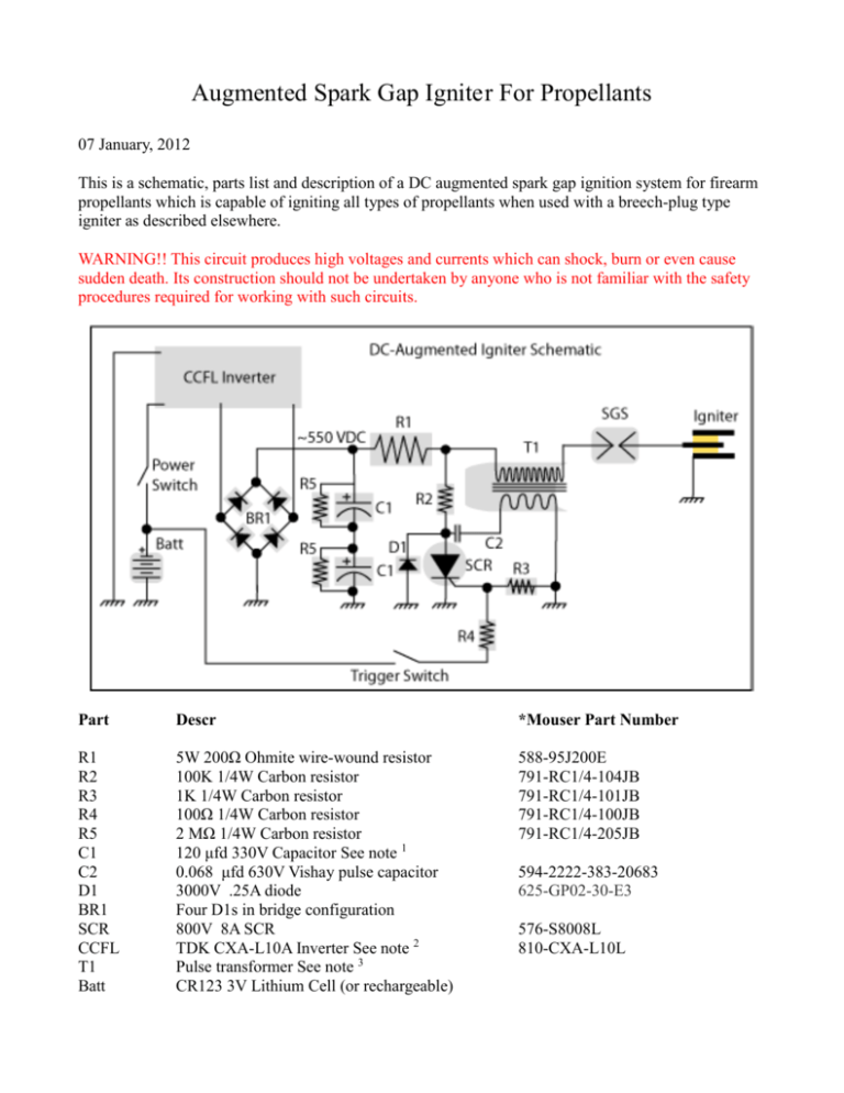
Augmented Spark Gap Ignite r For Propellants 07 January, 2012 This is a schematic, parts list and description of a DC augmented spark gap ignition system for firearm propellants which is capable of igniting all types of propellants when used with a breech-plug type igniter as described elsewhere. WARNING!! This circuit produces high voltages and currents which can shock, burn or even cause sudden death. Its construction should not be undertaken by anyone who is not familiar with the safety procedures required for working with such circuits. Part Descr *Mouser Part Number R1 R2 R3 R4 R5 C1 C2 D1 BR1 SCR CCFL T1 Batt 5W 200Ω Ohmite wire-wound resistor 100K 1/4W Carbon resistor 1K 1/4W Carbon resistor 100Ω 1/4W Carbon resistor 2 MΩ 1/4W Carbon resistor 120 μfd 330V Capacitor See note 1 0.068 μfd 630V Vishay pulse capacitor 3000V .25A diode Four D1s in bridge configuration 800V 8A SCR TDK CXA-L10A Inverter See note 2 Pulse transformer See note 3 CR123 3V Lithium Cell (or rechargeable) 588-95J200E 791-RC1/4-104JB 791-RC1/4-101JB 791-RC1/4-100JB 791-RC1/4-205JB 594-2222-383-20683 625-GP02-30-E3 576-S8008L 810-CXA-L10L Mouser Electronics (http://www.mouser.com) can supply most components. Note 1: Obtain from disposable camera flash units. Many can be found on eBay or from electronic surplus houses. Note 2: There are two modifications required. First, the output must be floated from the input. There is a wire jumper on the side marked 'GND' which must be removed. See photo below Second, the output must be taken from directly across the secondary transformer windings, not from the output capacitors. This can be done by either bridging the capacitor or by wiring directly to the transformer. Note 3: The pulse transformer was made by winding a primary and secondary over a plastic bobbin containing a 10mm ferrite rod (look in eBay). I designed the custom bobbin, which you can either machine from acetal or (even better) have it 3D-printed by Shapeways (http://www.shapeways.com). To get this printed, download the file and then upload it to Shapeways. They will print it and send it to you for a nominal fee. The primary is wound with five layers of #30 enameled wire, with each layer being epoxied and separated by either one thickness of one mil Mylar or two thicknesses of standard weight paper. The wire ends should be soldered to the output leads and then buried into the channels in the bobbin. The secondary is then covered and epoxied with either two layers of Mylar or four layers of paper, and then the secondary is wound with eight spaced turns of #24 enameled wire.
