Understanding DNS Services
Learning Objectives:
•
Observe DNS record types and functionality
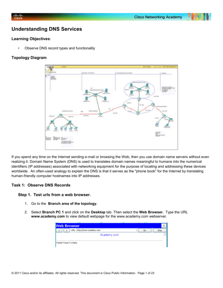
Topology Diagram
If you spend any time on the Internet sending e-mail or browsing the Web, then you use domain name servers without even
realizing it. Domain Name System (DNS) is used to translates domain names meaningful to humans into the numerical
identifiers (IP addresses) associated with networking equipment for the purpose of locating and addressing these devices
worldwide. An often-used analogy to explain the DNS is that it serves as the "phone book" for the Internet by translating
human-friendly computer hostnames into IP addresses.
Task 1: Observe DNS Records
Step 1. Test urls from a web browser.
1. Go to the Branch area of the topology.
2. Select Branch PC 1 and click on the Desktop tab. Then select the Web Browser. Type the URL
www.academy.com to view default webpage for the www.academy.com webserver.
© 2011 Cisco and/or its affiliates. All rights reserved. This document is Cisco Public Information. Page 1 of 23
3. Close and reopen the web browser and type ns.academy.com (without the www) into the web browser.
4. Close and reopen the web browser. Type academy.com into the web browser. That entry will not produce a
web page.
Step 2. View DNS Records.
1.
2.
3.
4.
Go to the Headquarters Campus Network.
Write down the ip address of the ns.academy.com server. ________________
Write down the ip address of the www.academy.com server. ________________
Select the ns.academy.com DNS server located in the Headquarter Campus Network and click on the Config
tab. Then select DNS from the list of Services and examine the DNS records.
5. Notice that there are different types of DNS records.The DNS records in this activity maps the names to an IP
address (type = A record).
6. Let’s create an alias that maps to another name (type = CNAME). Map www.ns.academy.com to
ns.academy.com. (See graphic below.) Click on Add.
7. When finished, go back to the Branch PC 1 and try the new DNS entry.
8. Go back to the ns.academy.com server. Look at the entry for academy.com. Use the Internet. What does SOA
stand for? ___________________
The URL ns.academy.com is translated into the IP address 192.0.2.68, which is the IP address of the Internal DNS. Next,
look at the other URL, www.ns.academy.com . It is translated into the URL ns.academy.com. The URL
www.ns.academy.com was created as a CNAME type (Canonical name record), which basically serves as an alias. So, as
was illustrated, ultimately, both URLs will be translated into the same IP address.
© 2011 Cisco and/or its affiliates. All rights reserved. This document is Cisco Public Information. Page 2 of 23
Step 3. View DNS records from another DNS server.
1. Select Branch PC 1 and click on the Desktop tab. Then select the Web Browser. Type the URL
www.isp.com to view default webpage for the isp.com webserver.
2. Go to the ISP Data Center.
3. Select the ns.isp.com DNS server and click on the Config tab. Choose the DNS service and add an entry into
the database to redirect the URL www.ispdata.com to www.isp.com. Use the information shown below to
create the new entry. Click Add when finished.
a) Name = www.ispdata.com
b) Type = CNAME
c) Host = www.isp.com
4. Type the URL www.ispdata.com to view default webpage for the www.isp.com webserver. The page should
be displayed this time.
Step 4. Observe DNS information using the nslookup command.
1. Select the Branch PC 1 and click on the Desktop tab. Then select the Command Prompt. Type the command
nslookup www.academy.com. Observe the output received.
PC>nslookup www.academy.com
Server: [192.0.2.68]
Address: 192.0.2.68
Non-authoritative answer:
Name: www.academy.com
Address: 192.0.2.69
2. Type the command nslookup academy.com from Branch PC1 Command Prompt. Observe the output
received.
PC>nslookup ns.academy.com
Server: [192.0.2.68]
Address: 192.0.2.68
Non-authoritative answer:
© 2011 Cisco and/or its affiliates. All rights reserved. This document is Cisco Public Information. Page 3 of 23
Name: ns.academy.com
Address: 192.0.2.68
Do you see any differences in the output between the two URLs? __________________________________________
What is different in the two outputs? _________________________________________________________________
______________________________________________________________________________________________
Step 5. Defining DNS record type available in this activity.
1. Select the ns.academy.com DNS server and click on the Config tab. Choose the DNS service. List the
different type of DNS entries that are available in this activity. Search the Internet and give a brief definition of
each record type.
________________________________________________________________________________________
________________________________________________________________________________________
________________________________________________________________________________________
________________________________________________________________________________________
________________________________________________________________________________________
________________________________________________________________________________________
________________________________________________________________________________________
________________________________________________________________________________________
________________________________________________________________________________________
________________________________________________________________________________________
________________________________________________________________________________________
________________________________________________________________________________________
________________________________________________________________________________________
________________________________________________________________________________________
________________________________________________________________________________________
________________________________________________________________________________________
________________________________________________________________________________________
________________________________________________________________________________________
________________________________________________________________________________________
________________________________________________________________________________________
________________________________________________________________________________________
________________________________________________________________________________________
________________________________________________________________________________________
________________________________________________________________________________________
© 2011 Cisco and/or its affiliates. All rights reserved. This document is Cisco Public Information. Page 4 of 23
Understanding e-mail Services
Learning Objectives:
•
•
•
•
Create e-mail accounts for users on the Mail Server
Setup client e-mail information on workstations
Observe sending and receiving e-mails
Observe e-mail SMTP and POP3 functionality
Topology Diagram
Step 1. Create e-mail accounts on the Mail Server.
1. Within the Head Quarter – Campus Network, select the email.academy.com Mail Server and click on the
Config tab. Then click on Email.
2. Verify that SMTP and POP3 services are on.
3. Notice the Domain Name for the Mail Server is email.academy.com and there are two users.
4. Create an additional e-mail account for User Three and then click on the
a. User = user3
b. Password = pass3
5. Create an e-mail account for User Four and then click on the
a. User = user4
b. Password = pass4
button to add the account.
button to add the account.
© 2011 Cisco and/or its affiliates. All rights reserved. This document is Cisco Public Information. Page 5 of 23
Step 2. Setup client e-mail information on workstations.
1. Select Branch PC 1 and click on the Desktop tab. Then click on Email and choose the Configure Mail button.
Write down some notes that will help you set up user3 and user4.
2. Go to PC0 in the branch office. and click on the Desktop tab. Then click on Email and choose the Configure
Mail button:
a. Your Name = User Three
b. E-mail Address = user3@email.academy.com
c. Incoming Mail Server (POP3) = email.academy.com
d. Outgoing Mail Server (SMTP) = email.academy.com
e. User Name = user3
f. Password = pass3
3. After the e-mail client information is entered, click the Save botton.
4. Select PC1 in the branch office and click on the Desktop tab. Then click on Email and choose the Configure
Mail button.
5.
Configure the e-mail client with the following information:
a. Your Name = User Four
b. E-mail Address = user4@email.academy.com
c. Incoming Mail Server (POP3) = email.academy.com
d. Outgoing Mail Server (SMTP) = email.academy.com
e. User Name = user4
f. Password = pass4
6. After the e-mail client information is entered, click the Save botton.
Step 3. Send an email to a user in the same domain.
1. Select Branch PC 1 and click on the Desktop tab. Then click on Email and choose Receive button to verify if
there is any unreceived mail in the Mailbox. If this is the first time for the client to communicate with the e-mail
server, it will take a little while for DNS to resolve the name. Observe the process in the lower portion of the Mail
Browser window.
2. There should be no new mail at this time.
3. Select the Compose button and send yourself an email using the address user1@email.academy.com. Again,
note the process in the lower portion of the Mail Browser window.
4. Select the Receive Button to receive the email. You should now see the e-mail. Double click on the message to
view the e-mail, then close the e-mail.
5. From Branch PC 1 compose and send an email to user3@email.academy.com.
6. Select PC0 and click on the Desktop tab. Then click on Email and choose the Receive button to receive the
email. View the e-mail and then close the Message window.
Step 4. Send an email to a user in a different domain.
1. Select Branch PC 1, the Desktop tab, Email. Select the Compose button and send an email to
user1@email.isp.com.
2. Select Laptop0 in the Home Office and configure the email client by entering the following information:
a. Your Name: Laptop User
b. Email Address: user1@email.isp.com
c. Incoming Mail Server: email.isp.com
d. Outgoing Mail Server: email.isp.com
e. User Name: user1
© 2011 Cisco and/or its affiliates. All rights reserved. This document is Cisco Public Information. Page 6 of 23
f. Password: pass1
g. SAVE
3. In the Configure Mail window and select the Receive button to receive the email. View the e-mail and then
close the Message window.
Step 5. Observe output when email is sent to the wrong address.
1. Select Branch PC 1, the Desktop tab, Email. Select the Compose button, then send an email to
user5@email.isp.com. Notice in the lower portion of the Mail Browser window that the message was
successfully sent.
2. On the Branch PC 1 click on the Receive tab to observe the content of the message you receive from the email
server.
Error message should appear similar to below:
This response was received because no such user existed in the domain. Error messages, which may seem
unimportant to end users can often provide useful information to the network administrator.
© 2011 Cisco and/or its affiliates. All rights reserved. This document is Cisco Public Information. Page 7 of 23
Step 6. Observe e-mail traffic in the Simulation Mode
1. Select the Simulation Mode tab to view additional protocol information used in this activity.
2. Select Branch PC 1, the Desktop tab, Email. Select the Compose button, then send an email to
user2@academy.com.
3. After clicking the Send button, click on the Auto Capture / Play button to begin the process on sending the email.
4. Observe the packets that are sent. The DNS packet are used to resolved the domain to an IP address. The
SMTP packets deliver the e-mail to the server.
5. After observing the simulation, click the Clear Event List button.
6. Now select Branch PC 2, the Desktop tab, Email. Select the Receive button.
7. After clicking the Receive button, click on the Auto Capture / Play button to begin the process on receiving the
e-mail.
8. Observe the packets that are sent. The DNS packet are used to resolved the domain to an IP address. The
POP3 packets are used to retrieve the e-mail to the server.
© 2011 Cisco and/or its affiliates. All rights reserved. This document is Cisco Public Information. Page 8 of 23
Understanding FTP Services
Learning Objectives:
•
•
•
Create a user name and password for authentication on the FTP Server
Access an FTP Site
Observe FTP download and upload functionality
Topology Diagram
File Transfer Protocol (FTP) is a network protocol used to copy a file from one host to another over a TCP-based network,
such as the Internet. FTP is built on a client-server architecture In order to do this an FTP server needs to be running and
waiting for incoming requests. The client computer is then able to communicate with the server.
Step 1. Create a user name and password for authentication on the FTP Server.
1. Select the ftp.academy.com server located in the Head Quarters area and click on the Config tab. Then select
the FTP service.
2. Verify that the FTP service is turned on.
3. Use the information below to create a NEW user name and password for authentication on the FTP Server:
a. User Name = user1
b. Password = cisco
c. Select all of the services. Write / Read / Delete / Rename / List
d. To add the login information, click on the
button
© 2011 Cisco and/or its affiliates. All rights reserved. This document is Cisco Public Information. Page 9 of 23
Step 2. Access an FTP Site.
1. Select Branch PC 1 and click on the Desktop tab. Then select the Command Prompt and type the command
ftp ftp.academy.com.
2. Authenticate with username user1 and the password cisco.
3. After you have logged in and successfully been authenticated the promt will change from PC> to ftp>.
Step 3. Observe the files on an FTP site from the FTP client.
1. After the client (Branch PC 1) has authenticated to the FTP Server, type the command help to view the
available ftp commands.
2. Type the command dir to view the files on the server.
Step 4. Rename a file on the FTP server.
1.
From the Branch PC 1, use the rename command to change the name of the myfile.txt file to chat.txt.
ftp> rename myfile.txt chat.txt
© 2011 Cisco and/or its affiliates. All rights reserved. This document is Cisco Public Information. Page 10 of 23
2. From the Branch PC 1 command prompt type the command dir. The file chat.txt should now be listed.
Step 5. Download a file from the ftp server and modify it on the PC. (Note: This step can take some
time.)
1. From the Branch PC 1 command prompt type the command get test.bin.
2. Close the Command Prompt and open the Text Editor application.
3. Click on File and select Open. Notice the test.bin file has been downloaded onto Branch PC1.
© 2011 Cisco and/or its affiliates. All rights reserved. This document is Cisco Public Information. Page 11 of 23
Step 6. Upload a file from a PC to an ftp server.
1. Open the Text Editor. Click on File and select New to create a new file. Type your name and your favorite color
in the text window.
2. Click on File and select Save. Save the file with the name mycolor.txt.
3. Close the Text Editor and open the Command Prompt. In the event the ftp session is closed repeat the
authentication process from to the ftp server (see Step 2).
4. From the Branch PC 1 type the command put myfile.txt. The file name is case sensitive.
5. Verify the new file has been uploaded to the ftp server by typing the command dir.
Optional – For additional practice, repeat Steps 1-6 using the ftp.isp.com server in the ISP located in the Data Centre
Network area.
© 2011 Cisco and/or its affiliates. All rights reserved. This document is Cisco Public Information. Page 12 of 23
Step 7: Copying a configuration from a router to an ftp server.
1. Select the Branch Office router and click on the CLI tab.
2. Access the priviledged mode configure and then enter the global configuration mode.
3. Use the following commands to set the username and password for ftp access to cisco.
BranchOffice(config)#ip ftp username user1
BranchOffice(config)#ip ftp password cisco
4. Exit the global configuration mode and save the running configuration to the ftp server.
BranchOffice#copy running-config ftp
Address or name of remote host [ ] ? 192.0.2.66
Destination filename [BranchOffice-confg]
Step 8: Verify that the configuration was saved on the ftp server
1. Select Branch PC 1 and open the Command Prompt. In the event the ftp session is closed repeat the
authentication process from to the ftp server (see Step 2).
2. Verify the new file (BranchOffice-confg) has been uploaded to the ftp server by typing the command dir.
3. As an alternate method of verifying that the new file was uploaded, select the ftp.academy.com server. Then
select the Config tab and choose FTP services. You should see the BranchOffice-confg file listed in the File
window.
Step 9: Copy a file from an ftp server to the running configuration of a router.
1. Select the Branch Office router and click on the CLI tab.
2. Access the priviledged mode.
3. Use the following command to copy the backup configuration file from the ftp server to the running configuration
on the BranchOffice router:
BranchOffice#copy ftp: running-config
Address or name of remote host [ ] ? 192.0.2.66
Destination filename [BranchOffice-confg]
Note: File name is case sensitive
Destination filename [running-config]? Press Enter to accept the default location
4. Transfer should be successful.
© 2011 Cisco and/or its affiliates. All rights reserved. This document is Cisco Public Information. Page 13 of 23
PT Master Topology – How to Conquer a Giant
Conquering VoIP
This activity uses the PT Master Topology to examine and configure VoIP. The additional items in the Master Topology
are placed in the clouds and are pre-configured to allow this lab to be fully functional.
Objectives
Become familiar with the new voice commands and voice devices in Packet Tracer 5.3
Gain experience with new technology and increase basic knowledge of netwok devices
Learn to configure basic CallManager Express commands and test connectivity
Step 1 Basic CallManager Express configuration
1. Open the file PT Master Topology.
2. On the HQCentralRouter use the CLI tab to look at the basic telephony services. Scroll to find the commands below:
HQCentralRouter(config)# telephony-service
HQCentralRouter(config-telephony)# max-ephones 9
HQCentralRouter(config-telephony)# max-dn 5
HQCentralRouter(config-telephony)# ip source-address 172.168.3.1 port 2000
HQCentralRouter(config-telephony)# auto-assign 1 to 5
HQCentralRouter(config-telephony)# exit
What do all these commands mean? Researching commands is a great way to learn. Here is a link to a telephony
command reference: http://www.cisco.com/en/US/docs/voice_ip_comm/cucme/command/reference/cme_cr.html
Document this information below.
HQCentralRouter(config)# telephony-service ___________________________
© 2011 Cisco and/or its affiliates. All rights reserved. This document is Cisco Public Information. Page 14 of 23
HQCentralRouter(config-telephony)# max-ephones 9 ______________________
HQCentralRouter(config-telephony)# max-dn 5 __________________________
HQCentralRouter(config-telephony)# ip source-address 172.168.3.1 port 2000 ________________________
HQCentralRouter(config-telephony)# auto-assign 1 to 5 ____________________________________
HQCentralRouter(config-telephony)# exit
Step 2 Basic directory number configuration
1.
On the HQCentralRouter configure ephone-dns (this command configures a directory number for an IP phone line,
intercom line, paging line, voice-mail port, or message-waiting indicator)
HQCentralRouter(config)# ephone-dn 1
HQCentralRouter(config-ephone-dn)# number 7891
HQCentralRouter(config)# ephone-dn 2
HQCentralRouter(config-ephone-dn)# number 7892
HQCentralRouter(config)# ephone-dn 3
HQCentralRouter(config-ephone-dn)# number 7893
HQCentralRouter(config)# ephone-dn 4
HQCentralRouter(config-ephone-dn)# number 7894
HQCentralRouter(config)# ephone-dn 5
HQCentralRouter(config-ephone-dn)# number 7895
2. Add a directory number for ephone-dn 6. First you will need to change the max-dn.
Step 3 Basic ephone configuration
1. On the HQCentralRouter look at the following configuration statements.
HQCentralRouter(config)# ephone 1
HQCentralRouter(config-ephone)# mac-address 0050.0FCE.109A
HQCentralRouter(config-ephone)# type 7960
HQCentralRouter(config-ephone)# button 1:1
HQCentralRouter(config-ephone)# ephone 2
HQCentralRouter(config-ephone)# mac-address 0060.702C.054D
HQCentralRouter(config-ephone)# type 7960
HQCentralRouter(config-ephone)# button 1:2
HQCentralRouter(config-ephone)# ephone 3
HQCentralRouter(config-ephone)# mac-address 0090.2B5A.AEB2
HQCentralRouter(config-ephone)# type CIPC
HQCentralRouter(config-ephone)# button 1:3
HQCentralRouter(config-ephone)# ephone 4
HQCentralRouter(config-ephone)# mac-address 0060.7068.5BC8
HQCentralRouter(config-ephone)# type CIPC
© 2011 Cisco and/or its affiliates. All rights reserved. This document is Cisco Public Information. Page 15 of 23
HQCentralRouter(config-ephone)# button 1:4
HQCentralRouter(config-ephone)# ephone 5
HQCentralRouter(config-ephone)# mac-address 0003.E46B.869C
HQCentralRouter(config-ephone)# type CIPC
HQCentralRouter(config-ephone)# button 1:5
3. Match the mac-addresses to phones in the topology diagram.
4. What are the choices for “type” in Packet Tracer. Look at the “telephony command reference” link for
all of the different types.
Step 4 Connecting 7960 IP phones to Switch
1. What type of cable is used to connect the IP Phone Line 7891 to the port Fa0/2 on the 3560-24PS Multilayer Switch?
________________
Step 5 View ephone Configuration and Status
1. Utilize the show ephone command to view configuration information and status
HQCentralRouter# show ephone
2. Notice that ephone 3, 4, and 5 are DOWN (If ephone 1 and 2 are showing DOWN, wait a moment and try again.
Ephone 1 and 2 should be shown as IDLE).
ephone-3 Mac:0090.2B5A.AEB2 TCP socket:[1] activeLine:0 UNREGISTERED
mediaActive:0 offhook:0 ringing:0 reset:0 reset_sent:0 paging 0 debug:0 caps:8
IP:0.0.0.0 0 CIPC keepalive 43 max_line 2
button 1: dn 3 number 7893 CH1 DOWN
Why are these devices not up? _______________________________________________________
________________________________________________________________________________
3. The devices that correspond to ephone 3, 4 and 5 are PCs that are using Cisco IP Communicator which is
SoftPhone software. Click on the HQ-PC and go to the Desktop. Select Cisco IP Communicator (CIPC). This will
bring up the SoftPhone GUI. Note that the line number appears in the upper right corner.
4. Use the show ephone command to view configuration information and status. Notice that ephone 3 is now up and
in the IDLE state.
5. To observe the phone registration process, bring up the CLI window for HQ Central router. Enter the debug
command debug ephone register
HQCentralRouter# debug ephone register
6. Repeat the process for of activating the Cisco IP Communicator software on the Tablet PC and the PDA. Be sure
to have the HQ Central router CLI window open to observe the output from the debug command.
7. Turn off all possible debugging with the undebug all command.
HQCentralRouter# undebug all
Step 6 Basic Dial Peer configuration
To enable calls from the Branch and Home Office, configure dial peers on the HQCentralRouter.
1. Configure a dial peer to the Branch Office router to call the two 7960 phones at 1101 and 1102
© 2011 Cisco and/or its affiliates. All rights reserved. This document is Cisco Public Information. Page 16 of 23
HQCentralRouter(config)# dial-peer voice 1 voip
HQCentralRouter(config-dial-peer)# destination-pattern 11..
HQCentralRouter(config-dial-peer)# session target ipv4:192.168.2.1
© 2011 Cisco and/or its affiliates. All rights reserved. This document is Cisco Public Information. Page 17 of 23
2. Configure a dial peer to the Home Office router to call the CIPC at 2201 and the Analog Telephone Adapter
(ATA) at 2202
HQCentralRouter(config)# dial-peer voice 2 voip
HQCentralRouter(config-dial-peer)# destination-pattern 22..
HQCentralRouter(config-dial-peer)# session target ipv4:192.0.2.18
Step 7 Test Voice Configuration
Test dialing from devices on the same CallManagers and between CallManagers
Note – you will want to have sound on for testing (Options Preferences Play Sound)
Testing the voice connection between the two 7960 phones on the HQCentralRouter
1. Click on the 7960 IP Phone labeled ‘Line 7891’
2. Select the GUI tab
3. Click on the phone headset – it is now offhook
4. Dial 7892 on GUI number pad – you will hear the phone start ringing
5. Click on the 7960 IP Phone labeled ‘Line 7892’
6. Select the GUI tab
7. Click on the phone headset to answer the phone
8. Click on the colored boxes in the upper right to generate tones across the call
9. Click on the headset to disconnect the call on both phones
Testing the voice connection between a 7960 phone and the Cuis on the
HQCentralRouter
1. Click on the Cuis 7894
2. Select the Desktop tab, select Cisco IP Communicator
© 2011 Cisco and/or its affiliates. All rights reserved. This document is Cisco Public Information. Page 18 of 23
3. Click on the ‘NewCall’ soft button
4. Dial 7891 on GUI number pad – you will hear the phone start ringing
5. Click on the 7960 IP Phone labeled ‘Line 7891’
6. Select the GUI tab
7. Click on the phone headset to answer the phone
8. Click on the colored boxes in the upper right to generate tones across the call
9. Practice dialing between the 7960 IP Phone ‘Line 7891’ and the 7960 IP Phone on the Branch Office router at 1101
10. Practice dialing between the 7960 IP Phone ‘Line 7891’ and the analog device on the Home Office router at 2202
11. Activate the CIPC on the laptop ‘Line 2201’ and practice dialing between the 7960 IP Phone ‘Line 7891’ and the
laptop
Step 8 Setting up additional IP phones
1. Add two 7960 phones to the topology in the Branch Office area
2. Connect the 7960 phones to the Branch Office multilayer switch
3. Examine the telephony configuration on the Branch Office router (shown below) and configure additional
IP phones with similar commands
dial-peer voice 1 voip
destination-pattern 78..
session target ipv4:192.168.2.2
!
dial-peer voice 2 voip
destination-pattern 22..
session target ipv4:192.0.2.18
!
telephony-service
auto-reg-ephone
max-ephones 4
max-dn 4
ip source-address 192.168.1.1 port 2000
!
The router is already configured for a
maximum of 4 phones, so no change will
need to be made to the max-ephones or maxdn commands.
© 2011 Cisco and/or its affiliates. All rights reserved. This document is Cisco Public Information. Page 19 of 23
ephone-dn 1
number 1101
!
ephone-dn 2
number 1102
!
ephone 1
device-security-mode none
mac-address 0002.177A.5575
type 7960
button 1:1
!
ephone 2
device-security-mode none
mac-address 0001.4308.1777
type 7960
button 1:2
Hint: New phone information that will need to
be added will be similar to these commands.
You may also want to examine the telephony
configuration the HQ Central router.
4. The third phone will be assigned the line number 1103
5. The fourth phone will be assigned the line number 1104
6. Roll over the phones to identify the MAC address information needed for the configuration.
Third phone MAC address: ____________________________________________
Fourth phone MAC address: ___________________________________________
7. Examine the Branch Office multilayer switch configuration. The interfaces that the two new phones are connected to
will need to be configured to carry voice traffic.
8. Once the all configuration is complete, click the Fast Forward Time button to update the devices.
9. Rollover the new phones and confirm that they have an IP address and line number.
10. Test the new phone by calling the other phones in the topology. All calls should be able to connect.
© 2011 Cisco and/or its affiliates. All rights reserved. This document is Cisco Public Information. Page 20 of 23
Final Configurations
Completed HQCentralRouter running configuration
HQCentralRouter# show running-config
<output omitted>
dial-peer voice 1 voip
destination-pattern 11..
session target ipv4:192.168.2.1
!
dial-peer voice 2 voip
destination-pattern 22..
session target ipv4:192.0.2.18
!
telephony-service
max-ephones 5
max-dn 5
ip source-address 192.168.3.1 port 2000
!
ephone-dn 1
number 7891
!
ephone-dn 2
number 7892
!
ephone-dn 3
number 7893
!
ephone-dn 4
number 7894
!
ephone-dn 5
number 7895
!
ephone 1
device-security-mode none
mac-address 0050.0FCE.109A
type 7960
button 1:1
!
ephone 2
device-security-mode none
mac-address 0060.702C.054D
type 7960
button 1:2
!
ephone 3
device-security-mode none
mac-address 0090.2B5A.AEB2
type CIPC
button 1:3
!
ephone 4
device-security-mode none
mac-address 0060.7068.5BC8
type CIPC
button 1:4
!
© 2011 Cisco and/or its affiliates. All rights reserved. This document is Cisco Public Information. Page 21 of 23
ephone 5
device-security-mode none
mac-address 0003.E46B.869C
type CIPC
button 1:5
!
line con 0
logging synchronous
line vty 0 4
login
!
end
Completed BranchOffice Router running configuration
BranchOffice# show running-config
<output omitted>
dial-peer voice 1 voip
destination-pattern 78..
session target ipv4:192.168.2.2
!
dial-peer voice 2 voip
destination-pattern 22..
session target ipv4:192.0.2.18
!
telephony-service
max-ephones 4
max-dn 4
ip source-address 192.168.1.1 port 2000
!
ephone-dn 1
number 1101
!
ephone-dn 2
number 1102
!
ephone-dn 3
number 1103
!
ephone-dn 4
number 1104
!
ephone 1
device-security-mode none
mac-address 0002.177A.5575
type 7960
button 1:1
!
ephone 2
device-security-mode none
mac-address 0001.4308.1777
type 7960
button 1:2
!
© 2011 Cisco and/or its affiliates. All rights reserved. This document is Cisco Public Information. Page 22 of 23
ephone 3
device-security-mode none
mac-address 00E0.F906.821A
type 7960
button 1:3
!
ephone 4
device-security-mode none
mac-address 0003.E480.6BD3
type 7960
button 1:4
!
line con 0
line vty 0 4
login
!
end
MAC addresses will vary.
Completed Branch Office switch running configuration
Switch#show running-config
<output omitted>
interface FastEthernet0/1
switchport voice vlan 1
!
interface FastEthernet0/2
switchport voice vlan 1
!
interface FastEthernet0/3
switchport voice vlan 1
!
interface FastEthernet0/4
switchport voice vlan 1
!
interface FastEthernet0/5
switchport voice vlan 1
Interfaces may vary depending on where the
cables are connected.
© 2011 Cisco and/or its affiliates. All rights reserved. This document is Cisco Public Information. Page 23 of 23


