Using Parametric Equations in SolidWorks, Example 1
(Draft 4, 10/25/2006, SW 2006)
Introduction
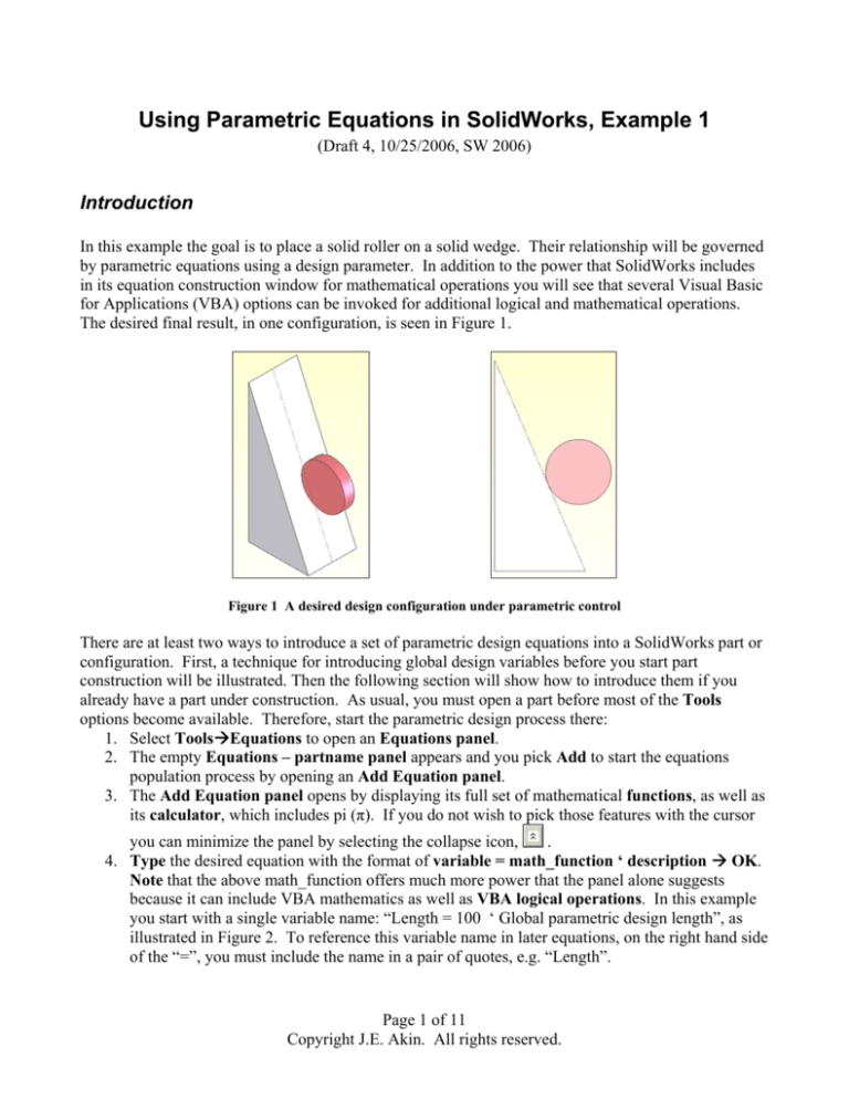
In this example the goal is to place a solid roller on a solid wedge. Their relationship will be governed
by parametric equations using a design parameter. In addition to the power that SolidWorks includes
in its equation construction window for mathematical operations you will see that several Visual Basic
for Applications (VBA) options can be invoked for additional logical and mathematical operations.
The desired final result, in one configuration, is seen in Figure 1.
Figure 1 A desired design configuration under parametric control
There are at least two ways to introduce a set of parametric design equations into a SolidWorks part or
configuration. First, a technique for introducing global design variables before you start part
construction will be illustrated. Then the following section will show how to introduce them if you
already have a part under construction. As usual, you must open a part before most of the Tools
options become available. Therefore, start the parametric design process there:
1. Select ToolsÆEquations to open an Equations panel.
2. The empty Equations – partname panel appears and you pick Add to start the equations
population process by opening an Add Equation panel.
3. The Add Equation panel opens by displaying its full set of mathematical functions, as well as
its calculator, which includes pi (π). If you do not wish to pick those features with the cursor
.
you can minimize the panel by selecting the collapse icon,
4. Type the desired equation with the format of variable = math_function ‘ description Æ OK.
Note that the above math_function offers much more power that the panel alone suggests
because it can include VBA mathematics as well as VBA logical operations. In this example
you start with a single variable name: “Length = 100 ‘ Global parametric design length”, as
illustrated in Figure 2. To reference this variable name in later equations, on the right hand side
of the “=”, you must include the name in a pair of quotes, e.g. “Length”.
Page 1 of 11
Copyright J.E. Akin. All rights reserved.
Figure 2 Starting the parametric design variable first
5. This equation then appears in the prior Equations panel as active equation number 1, as seen
in the top of Figure 3. SolidWorks has also automatically added quotes around the variable
name (so you can later use it on the right hand side of a later equation). The equation can be
deleted or edited in that panel by selecting the corresponding tab. You would select Add to
continue the equation population process. Assume you plan for a second global variable by
repeating the above procedure and type in a definition of the roller diameter as:
Roller_Dia = 14 ‘ Optional rollre parameter.
6. If you fail to notice a typing error above you simply correct it later by highlighting the second
equation and select Edit in the Equations panel to place the equation in the Edit Equation
panel where the required changes are made and accepted (see bottom of Figure 3).
7. Exit the Equations panel and Rebuild the part to activate your equations. If you want to
suppress (or unsuppress) an equation simply change the check-box status in front of the
equation number.
In this discussion, the term “global variable” might mean global for this configuration only, or also
global in other specific design configurations. Figure 4 shows the above two equations in the
Equations panel. In that panel you can pick the Configs tab to define the scope of your design
variables. The captions for the three possible scope choices are self explanatory.
Page 2 of 11
Copyright J.E. Akin. All rights reserved.
Figure 3 The second design variable
Figure 4 Configurations governed by these two variables
You could continue to add equations in a similar way. Instead, the following section will show how to
create equations as you build a part (or add them to an existing part).
Constructing the parametric triangular configurations
The construction will be quite simple geometrically. Open a new part. From the front plane origin
construct the horizontal and vertical lines and then close the triangle. Most designs will be parametric
and are defined by one or more “global variables”. This design will be governed by two design
parameters; global variables “Angle”, and “Length”. The process requires that you be able to select
and name various dimensions. To do that in any drawing you will need to show the feature
dimensions, along with their names. Each line (or extrusion thickness, etc.) is given a default
dimension name and value when it is created. All dimensions and names will appear in each view.
That can result in a very cluttered image when a part has many features. You can right click on
unwanted items and select “hide” to unclutter the display. Better still, would be to hide each feature
Page 3 of 11
Copyright J.E. Akin. All rights reserved.
dimension and name after they are created, if you know they will not be changed by the parametric
design variables. Typically, fillets would be such a feature.
Begin the part construction by turning on the option to display names:
1. Select ToolsÆOptionsÆSystem OptionsÆShow dimension namesÆOK
2. In the Feature Manager right click on AnnotationsÆShow Feature Dimensions.
3. Sketching in the front plane, draw a horizontal line from the origin to serve as the base of the
triangle. Use Smart Dimensions to show the length you drew and the default name that SW
has assigned to that dimension.
4. Double click on that dimension so that the Modify panel opens, as seen in Figure 5. Rather
than change the number, click on the down arrow for available options.
5. Select Add Equation. Since there are currently no equations defined SW jumps to the Add
Equation panel of the Equations panel. The default name (in quotes) of the selected
dimension automatically appears, to start the equation.
6. Type in the dimension length of 100 (“D1@Sketch1” = 100), or utilize the calculator pad,
OK. Notice, in Figure 6, that the default dimension name (D1) is followed by an “@”,
followed by the default sketch name. Other needed names can be appended by SW to that
current string.
Figure 5 Defining the line length with an equation
Figure 6 Setting a dimension with an equation
Page 4 of 11
Copyright J.E. Akin. All rights reserved.
You could view the above steps as an indirect way to insert global design variables. To do that:
1. In the Equations panelÆEdit All (see Figure 6) to open an edit panel.
2. In Edit Equation type Length = 100 ‘ Global variable, OK. This makes the new equation
appear in the Equations panel. It is placed at the top of the list since it does not reference any
names on the right of “=”. Select Edit All again.
3. In Edit Equations highlight the previous length (100) and replace it with Length (Figure 7).
Figure 7 Defining and citing a global variable
These two equations have not been activated yet (by a Rebuild). Before doing that the sketch will be
renamed (to reduce the length of the equation), and the dimension will be renamed to enhance clarity
of the equation:
1. Use a slow double click on the name ‘Sketch1’ in the Feature Manager to replace the default
sketch name with ‘S_1’ or ‘S1’. Of course, if that sketch had a very important function you
might use a name longer than the original.
2. One way to change the dimension name is to right click in the graphics area and pick
Properties (while the dimension is highlighted) to open the Dimension Properties panel.
3. There type the desired name, say HorizontalÆOK, as seen in Figure 8
Figure 8 Changing the default name property of a dimension
While the name changes have taken effect, as seen in Figure 9, the equations have not since a Rebuild
command has not been issued. That is clear since the initial line length is unchanged as also seen in
Page 5 of 11
Copyright J.E. Akin. All rights reserved.
Figure 9, and because it does not have a preceding equation symbol,
command to activate the two equations.
. Now you issue a Rebuild
Figure 9 Active name changes but inactive equations
Next the vertical side of the triangle will have its dimension given a name, Vertical, as outlined above,
and will have the dimensions value determined by a logical VBA equation:
1. Draw the vertical side from the origin and close the triangle.
2. For the vertical side Smart DimensionsÆModifyÆAdd Equation (see Figure 10.)
Figure 10 Select an equation to define a dimension
3. The Add Equation panel appears with (the default prompt) “D1@S_1” =.
4. Insert a VBA iif statement to create an if-then-else numerical result, such as typing in
“D1@S_1” = IIF (Length > 100, 50, 150), setting the vertical dimension to 50 or 150 mm.
5. Next, change the default name from D1 to Vertical by using the Dimension Properties panel,
as described above (and in Figure 8). The last two steps are seen in Figure 11.
Figure 11 Using a VBA statement in a SolidWorks equation
Page 6 of 11
Copyright J.E. Akin. All rights reserved.
Again, this new equation will not take effect until a Rebuild command is issued. Before going on to
that step it will be useful to review some of the VBA enhancements and limitations related to equations
in SolidWorks.
Using VBA in SolidWorks equations
While the standard SW Add Equation panel offers a lot of power, it currently has some important
limitations. One is that the equation must occupy a single line (of unknown maximum length).
Another is that it omits a few useful mathematical operations. Finally, the availability of logical
functions seems to be missing and is only mentioned in three lines of the online help. Visual Basic for
Applications can help with all three shortcomings. The VBA iif function, known as the immediate if,
is a condensed one line version of an if-then-else logic with syntax: iif ( logical_expression,
result_if_true, result_if_false ). Figure 12 shows six different uses of iif, and seven mathematical
functions that supplement those listed in SW. The working logical operators in Figure 12 are not quite
what you would expect if you are familiar with VBA or engineering programming languages like
Fortran 95. Four logical operators that surprisingly fail in SW are given in Figure 13.
Figure 12 VBA logic and extra functions available for equations
One useful new mathematical operation, in Figure 12, is integer arithmetic division which is denoted
with the backslash (\). If you know VBA equation syntax you can always try it in an equation. If it is
not utilized in SW you will simply get “The syntax of this equation is incorrect” as an error message.
[The author believes that the SW equation parser has a logic error that allows only one “=” per
statement unlike VBA, C, Fortran, Java, etc. That would clearly explain the logic failures in Figure 13
and the need for “like” in Figure 12.]
Page 7 of 11
Copyright J.E. Akin. All rights reserved.
Figure 13 Unexpected VBA logic failures.
Secondary variables
Sometimes you may want to calculate items already available in SW so to have them handy in an
equation and to avoid trying to include menu picks. Such items might include the area, perimeter,
centroid, etc. Here the first two are used to illustrate combining named dimensions and the square root
function (sqr). The area calculation (with incorrect units display) is given in Figure 14 (after an edit,
not shown here, reduced the result_if_false from 150 to 145 mm). That figure serves as a reminder
that the user must assure every term in an equation has the same units. If the units displayed
incorrectly you could note that in the comment.
Figure 14 Adding an area calculation as Equation 4
Modifying controlling design variables
The modification of the base length global design parameter will be illustrated next (finally) to show
the effect of the base length logic on the part height:
1. If the Equations panel is still open simply highlight the first equation (Figure 15).
2. Otherwise use Feature ManagerÆEquationsÆEdit to open the Equation panel.
3. In the Edit Equation panel change the value of Length from 100 to 68 mm, OK.
4. Activate the modified equations with a Rebuild.
5. That results in the height becoming 145 mm, as seen in Figure 16
In Figure 16 notice that the height dimension is now preceded by the equation symbol to remind you
that it is governed by an equation. The perimeter calculation also appears in that figure.
Page 8 of 11
Copyright J.E. Akin. All rights reserved.
Figure 15 Changing the base design parameter
Figure 16 Parametric change in the triangle height
Next, the roller is to be placed tangent to the incline. The actual position will be set by the angle from
the origin to the center of the roller. That angle, named “Angle”, will be determined by a logical
operation (Figure 17).
Figure 17 Setting the roller angle via logic
When the editing of these six equations is completed, as seen in Figure 18, there are four possible sizes
for this pair of objects. The data and image for Length = 68 appear in the top and left center regions of
Page 9 of 11
Copyright J.E. Akin. All rights reserved.
Figure 18. The corresponding image and data for Length = 62 are seen in the middle right and bottom
regions, respectively of the same figure.
Figure 18 Two configurations based on the “Length” global variable
Driven dimensions
It is still possible to use driven dimensions in a part governed by equations. For example, assume you
need the center location of the roller. If you add a vertical dimension to that point the sketch turns red
and you get a warning that the requested information should be considered as a driven dimension.
Agreeing to that change allows the dimension to appear, but in a different color (gray here). Those
interactions are illustrated in Figure 19. Extruding the two regions with different thicknesses gives the
solids seen originally in Figure 1.
Closure
Clearly, some of the logic invoked in this example is not very practical and was chosen just to illustrate
the ability to use logic in the design process. The reader is encouraged to simply try generating various
forms of equations, as in Figure 12 and Figure 13, to verify that you understand the process. For
Page 10 of 11
Copyright J.E. Akin. All rights reserved.
example, try including the VBA line continuation symbol, “ _” (blank underscore), to use a second line
in an equation
Figure 19 Related driven dimension to roller center
References
1. TriAxial Design and Analysis, ”Adding Logic to Equations: How VBA can be utilized to do
amazing things”, SW Tips & Tricks, v. 4-07, July 2004.
2. TriAxial Design and Analysis, ”Links, Equations, and Design Tables”, SW Tips & Tricks, v. 202, April 2000.
3. W.E. Howard, J.C. Musto, “Use of Parametric Modeling Techniques”, in Introduction to Solid
Modeling Using SolidWorks, McGraw Hill, 2006.
4. M. Spens, Automating SolidWorks 2004 using Macros, SDC Publications, 2004.
5. SDRC, Exploring IDEAS Design, v. II, Structural Dynamics Research Corp., 1996.
Page 11 of 11
Copyright J.E. Akin. All rights reserved.


