Securitron Magnalock Corp.
Tel 800.624.5625
www.securitron.com
techsupport@securitron.com
ASSA ABLOY, the global leader
in door opening solutions
SECURITRON MODEL LMS-1, LML-1, LML-2 LATCH MONITOR
INSTALLATION AND OPERATING INSTRUCTIONS
1. DESCRIPTION
The latch monitor provides an SPDT dry output which
switches when a door is latched or unlatched. It can
also monitor a deadbolt. The most common use for
the latch monitor is to connect to an alarm system and
report on door status. When used in this way, the latch
monitor provides higher security assurance than the
more commonly employed magnetic contacts as they
can report a door as “closed” when it is still unlatched or
unbolted. A second use for the latch monitor is to
initiate delayed exit when the latch is withdrawn from
the inside on a door equipped with a Magnalock and
logic timing equipment.
MODEL
LML-1
The latch monitor mounts behind the strike plate and is therefore concealed for optimum
appearance. The three models differ as follows: The LMS-1 includes a single SPDT switch and is
sized for a 2 3/4” ANSI cut-out. The LML-1 includes a single switch and is sized for a 4 7/8”
ANSI cut-out. The LML-2 includes two separate switches and is sized for a 4 7/8” ANSI cut-out.
The LML-2 is capable of separately monitoring a latch and deadbolt.
2. PHYSICAL INSTALLATION
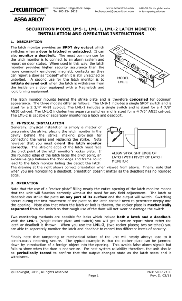
Generally, physical installation is simply a matter of
unscrewing the strike, placing the latch monitor in the
cavity behind the strike, making provision for
connecting the wires and replacing the strike. Note
however that you must orient the latch monitor
correctly. The straight edge of the latch must face
the pivot point of the latch monitor’s rocker plate. If
ALIGN STRAIGHT EDGE OF
the rounded edge of the latch faces the pivot point, an
LATCH WITH PIVOT OF LATCH
excessive gap between the door edge and frame could
MONITOR
lead to the latch monitor failing the detect the latch.
The drawing at the right shows correct orientation when viewed from above. Finally, note that
when you are monitoring a deadbolt, orientation doesn’t matter as the deadbolt has no rounded
edge.
3. OPERATION
Note that the use of a “rocker plate” filling nearly the entire opening of the latch monitor means
that the unit will function correctly without the need for any field adjustment. The latch or
deadbolt can strike the plate on any part of its surface and the output will switch. Switching
occurs during the first movement of the plate so the latch doesn’t need to penetrate deeply into
the opening. Note also that when the latch or bolt is thrown, the rocker plate is mechanically
separated from the switch so that rough use of the door will not wear or damage the switch.
Two monitoring methods are possible for locks which include both a latch and a deadbolt.
With the LML-1 (single rocker plate and switch) you will get a secure report when either the
latch or deadbolt is thrown. When you use the LML-2, (two rocker plates; two switches) you
are able to separately monitor the latch and deadbolt to record two different levels of security.
Finally note that tampering or mechanical failure of the unit will nearly always lead to it
continuously reporting secure. The typical example is that the rocker plate can be jammed
down by introduction of a foreign object into the opening. This avoids false alarm signals but
fails to show when the door is not secure. For best system reliability therefore, the unit should
be periodically tested to confirm that the output changes state as the latch seats and is
withdrawn.
© Copyright, 2011, all rights reserved
Page 1
PN# 500-12100
Rev. D, 03/11
4. WIRING
The latch monitor has three wires (per switch) that are assigned by color as follows:
White = Common
Red = N.C.
Black = N.O.
Because we’re using the terms normally open and normally closed, it’s necessary to define what
we mean by “normal”. The normal condition of the latch monitor is when it is reporting
secure (the latch or dead bolt is engaged). So, for example, you’ll read a closed circuit between
White and Red if you meter the unit in the secure condition (latch is engaged) but you’ll read
open if you meter it in the alarm condition (door is open). Maximum contact ratings are 2
Amps at 24V.
Securitron’s Latch Monitor series is covered under US patent #5,757,269
5. MAGNACARE LIFETIME REPLACEMENT WARRANTY
For warranty information visit www.securitron.com/en/site/securitron/About/MagnaCare-Warranty/
Page 2
PN# 500-12100
Rev. D, 03/11


