Datasheet - Pyramid Technical Consultants
advertisement
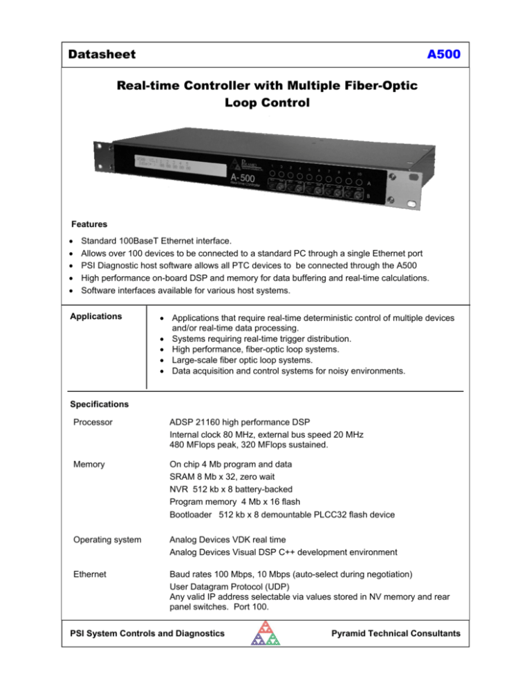
Datasheet A500 Real-time Controller with Multiple Fiber-Optic Loop Control Features • • • • • Standard 100BaseT Ethernet interface. Allows over 100 devices to be connected to a standard PC through a single Ethernet port PSI Diagnostic host software allows all PTC devices to be connected through the A500 High performance on-board DSP and memory for data buffering and real-time calculations. Software interfaces available for various host systems. Applications • Applications that require real-time deterministic control of multiple devices and/or real-time data processing. • Systems requiring real-time trigger distribution. • High performance, fiber-optic loop systems. • Large-scale fiber optic loop systems. • Data acquisition and control systems for noisy environments. Specifications Processor ADSP 21160 high performance DSP Internal clock 80 MHz, external bus speed 20 MHz 480 MFlops peak, 320 MFlops sustained. Memory On chip 4 Mb program and data SRAM 8 Mb x 32, zero wait NVR 512 kb x 8 battery-backed Program memory 4 Mb x 16 flash Bootloader 512 kb x 8 demountable PLCC32 flash device Operating system Analog Devices VDK real time Analog Devices Visual DSP C++ development environment Ethernet Baud rates 100 Mbps, 10 Mbps (auto-select during negotiation) User Datagram Protocol (UDP) Any valid IP address selectable via values stored in NV memory and rear panel switches. Port 100. PSI System Controls and Diagnostics Pyramid Technical Consultants Datasheet A500 Specifications (continued) Fiber-optic ports Five loop ports, each a transmitter / receiver pair. Expandable to ten ports with –R5T5 option.. Up to fifteen devices per port. Peer-to-peer A500 communication available through loop ports. Power input +24V (+/- 2V) DC, 500 mA (up to maximum 1000 mA depending on expansion boards). Controls Three 10 position rotary switches for setting last byte of IP address. Processor reset button. Displays 2 by 40 character backlit LCD on front panel for POST messages and connection status. Status LEDs on rear panel for power, device status and Ethernet baud rate. Case 19” rack mounting, 1U. Stainless steel sheet, with aluminium front panel, Weight 2.0 kg (4.4 lb) Operating environment 10 to 35C, < 80% humidity, non-condensing, vibration < 0.1g all axes, 1 to 1000Hz Storage environment 0 to 50C, < 80% humidity, non-condensing, vibration < 2g all axes, 1 to 1000Hz Interfacing Interfaces To host system: Ethernet 10/100baseT, UDP messaging. To front-end devices: Fiber-optic loop, 10 Mbit/sec serial, 9 bit asynchronous binary. Host computer PSI Diagnostic host software recommended. Libraries available for Microsoft® .NET 2.0, Win32 and LabVIEW. Connectors Ethernet RJ-45 socket, suitable standard Ethernet 8-way plug and CAT5 or higher cable. Fully transformer isolated Auto MDIX capability: The A500 negotiates TX and RX lines when making a connection. Either crossover or non-crossover cables may therefore be used. Fiber optics Five pairs (in base A500), 1mm Avago HFBR ST bayonet. Power in 2.1mm threaded jack. Mates with Switchcraft S761K or equivalent. PSI System Controls and Diagnostics Pyramid Technical Consultants Datasheet A500 LCD DISPLAY 43.7 (1U) 482.6 (19") +24VDC POWER IN FIBER-OPTIC TX (light gray) FIBER-OPTIC RX (dark gray) ETHERNET ADDRESS SELECTOR SWITCHES (3) RESET STATUS LEDs M4 GROUND LUG Dims mm Ordering information A500 A500 with PSI Diagnostic host software -R5T5 Add mezzanine board with five additional fiber optic receiver / transmitter pairs -R10 Add mezzanine board with the additional fiber optic receivers -G Add expansion board with four TTL trigger/gate inputs -GC Add expansion board with four TTL trigger/gate inputs and ten fast scaler inputs Pyramid Technical Consultants, Inc., 1050 Waltham Street Suite 200 Lexington MA 02421 USA Tel: +1 781 402 1700 (USA), +44 1273 493590 (UK) The information herein is believed accurate at time of publication, but no specific warranty is given regarding its use. All specifications are subject to change. Trademarks and copyright acknowledged. A500_DS_090813 Email: support@ptcusa.com www.ptcusa.com PSI System Controls and Diagnostics Pyramid Technical Consultants Datasheet A500 448.0 TOP 9.2 482.6 (19") 221.0 247.2 42.6 3.0 43.7 (1U) Dims mm PSI System Controls and Diagnostics Pyramid Technical Consultants Datasheet A500 Mezzanine board options -R5T5 Additional five pairs of receiver / transmitter pairs. Available to provide another five fiber-optic loops, or to provide dedicated functions such as optical trigger distribution. -R10 Additional ten fiber-optic receivers. Available for incoming data streams in special applications. FIBER-OPTIC RXTX OPTIONS LCD DISPLAY 43.7 (1U) 482.6 (19") PSI System Controls and Diagnostics FIBER-OPTIC TX (light gray) FIBER-OPTIC RX (dark gray) Pyramid Technical Consultants Datasheet A500 Expansion board options -G Four independent TTL gate trigger inputs, 50 ohm terminated. The A500 can be software configured to distribute these signals to fiber-optic transmitters on the –R5T5 or –T10 mezzanine board with any mapping. Propagation from input to optical output < 150 nsec. +24VDC POWER IN ETHERNET ADDRESS SELECTOR SWITCHES (3) RESET GATE CONNECTORS (4) STATUS LEDs M4 GROUND LUG -GC Four independent TTL gate trigger inputs (as –G option) plus ten fast pulse counterscaler channels, suitable for discriminated pulses from photomultipliers and similar devices. Counter-scaler inputs 50 ohm terminated, suitable for –1.6 V NIM pulses (32 mA). Smallest detectable pulse height –0.45 V. Minimum detectable pulse width 5 nsec. Pulse pair resolution 10 nsec. Scaler depth 32 bits (background readout possible). Integration period adjustable 100 µsec to 60 sec. Multiple integration trigger modes. +24VDC POWER IN ETHERNET ADDRESS SELECTOR SWITCHES (3) RESET COUNTER CONNECTORS (10) GATE CONNECTORS (4) STATUS LEDs M4 GROUND LUG -xxx New expansion boards can be designed to particular customer requirements. Please contact Pyramid Technical Consultants to discuss you application. PSI System Controls and Diagnostics Pyramid Technical Consultants

