Rotating Electrical Machines
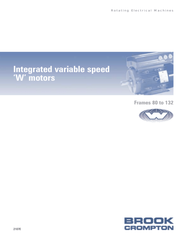
Integrated variable speed
‘W’ motors
Frames 80 to 132
2107E
2107E Issue 1
Integrated variable speed ‘W’ motors
Variable speed motors
0.55kW to 7.5kW
designs and installations. The close electrical
Brook Crompton
Quality assurance
Brook Crompton is a leading manufacturer of
Stringent quality procedures are observed
and mechanical coupling of the inverter and
electric motors for the global industrial
from first design to finished product in
motor means there is no need for extra
market, with motor solutions which benefit a
accordance with the ISO9001 documented
cabling, so you can avoid EMC problems and
wide range of customers.
quality systems.
voltage spikes. It’s efficient, robust and
Our products are used in almost every
Variable speed motor range
industrial activity including water treatment,
Brook Crompton’s fully integrated variable
and its fast user-friendly programming means
building services, chemical/petrochemicals,
speed ‘W’ motor (VSM), offers the reliability,
that installation is simple and fast.
general processing and manufacturing
low noise and energy saving characteristics
where they drive fans, pumps, compressors
you’ve come to expect from the ‘W’ range,
Whether you need fine speed control, rapid
and conveyors, amongst other things.
but with added technology.
response and acceleration, energy efficiency
Brook Crompton incorporates many well
The VSM’s perfectly matched motor and
known names including Brook Motors,
inverter has been designed to improve the
Crompton Parkinson, Electrodrives,
performance of machinery and mechanical
Efficiency
Newman, Bull Electric and Hawker Siddeley
handling systems as well as increase the
Brook Crompton are an approved
Electric Motors.
efficiency and reduce the cost of fan and
manufacturer of ac electric motors within the
pump systems.
UK Government’s Enhanced Capital
economical - in short - everything you’d
expect from a motor with the ‘W symbol -
or low noise operation, you’ll find it all in the
Allowance (ECA) scheme.
We have extensive stocks of motors around
2
VSM ‘W’ package.
the world, backed-up by a network of
The VSM package fits within the same
distributors, ensuring excellent local support
envelope as the equivalent ‘W’ motor, and
A wide range of single and multi-speed
wherever needed.
has the same facility for mounting the
motors are included on the UK Energy
terminal box (now the inverter) on the top or
Technology List in addition to the VSM.
the side of the motor. This allows for
Please check the ECA scheme website:
considerable space-saving and flexibility, for
www.eca.gov.uk at time of purchase for
example, in fitting the motor to existing
current listing.
2107E Issue 1
Integrated variable speed ‘W’ motors
VSM benefits and options
Cost saving
VSM mounted controls options
Enclosure options
◆ no screened power cable required
A variety of components can be locally
◆ IP protection ratings to suit customer
◆ no cable length limitation, hence no cable
mounted and fully wired to a 3-station die
chokes required
Complete flexibility
requirements
cast aluminium enclosure to provide control
◆ cost-effective pressed or sheet steel
at the motor itself. Choose from any 3 of the
◆ polycarbonate, polyester, stainless steel
following:
etc
◆ specially designed and fabricated to
◆ option available of three inverter positions
◆ stop push button
specification
◆ start push button
◆ speed control potentiometer
Control options
◆ forward/reverse selector switch
◆ open loop - local or remote operation
◆ local/remote selector switch
◆ closed loop process PID control -
◆ indicator lamp
pressure/ flow/temperature
◆ low/high speed selector switch
◆ closed loop speed control
◆ manual/automatic selector switch
◆ single or multi-motor control - eg duty
Mechanical options
◆ energy saving ‘sleep’ mode at zero
standby/assist/share
The VSM can be fitted with all the normal
motor extras. It can also offer customised
solutions, for example:
Space saving
◆ no panel space required
◆ VSM is the same size as a standard ‘W’
motor
demand
◆ analogue, digital, RS485 or Profibus
control
◆ complete switchgear, control and
◆ quick release shaft system - paint paddle
mixers etc
◆ specified paint colours and special
coatings
◆ special shafts
protection equipment
◆ simple control components - stop, start,
potentiometer, lamps etc
◆ PLCs, intelligent HMI and operator
interfaces with customised menus
◆ sensors and transducers - 0.10V, 4-20mA,
Complete variable speed
solutions
pressure, flow, temperature etc
◆ remote control stations
We can offer completely engineered
variable speed motor systems to provide
specific customer solutions from one single
source.
Typical applications include:
◆ pumps
◆ compressors
◆ fans
◆ mixers
◆ conveyors
Typically, a matched package of equipment
may consist of:
Variable speed motor replacing mechanical variator
◆ VSMs
◆ complete control panel
◆ customer interfacing
◆ feedback device
3
2107E Issue 1
Integrated variable speed ‘W’ motors
Specifications
◆ Totally enclosed fan ventilated (TEFV)
Technical data
Standards
Number of programmable
inputs/outputs
◆ Safety: EN60146, EN61800-2, EN50178,
◆ 4 digital inputs
◆ Anodised aluminium riveted nameplate
◆ 1 pulse input
◆ Water-based paint - water blue RAL 5021
EN60204, UL508
◆ EMC: EN61800-3, EN50081, EN50082
polypropylene fan, black steel fan cover
◆ 1 analogue voltage input
Protection
◆ 1 digital/analogue output
Optional Features
◆ 7 preset speeds
◆ IP66 enclosure
◆ Forced ventilation
◆ In-built thermal overload protection of
◆ Special bearings and locations
External conditions
motor and electronics
◆ IP55 enclosure
◆ Standard and non-standard mountings
under/overvoltage, overcurrent and voltage
◆ 2.5g vibration test (IEC 68)
◆ Special shafts
transients
◆ 93% (+2%, -3%) max storage relative
◆ Profibus version
◆ In-built protection against missing phase,
◆ RFI class 1B
humidity
Mains supply
◆ Max 40°C (over 24 hours average) ambient
parameters
temperature without derating
◆ 380-480 volts, ±10%
◆ 50-60Hz supply frequency
◆ Min -10°C ambient temperature
◆ Maximum imbalance ±2% of rated supply
◆ -25 +65/70°C during storage
◆ Mechanical brakes
◆ Max 1000m above sea level before derating
voltage
Accessories
◆ Potentiometer in gland
◆ Power factor/cos Ø 0.881/1.0 at rated load
◆ Local operating pad (LOP)
◆ 1 time/2 min switches on supply input
Standard specification
◆ 4mm2 power terminals
◆ Top mounted aluminium inverter box, black
aluminium lid, standard inverter fitted with
Control characteristics
◆ Customer factory settings of inverter
◆ Local control panel (parameter change)
- remote kit
- gland plug kit
3 plastic blind plugs
◆ 0-132Hz frequency range
◆ Foot mounted (B3), detachable steel feet
◆ RS485/RS232 converter
◆ 0.1% resolution on output frequency
◆ Voltage 380-480 volts ±10%
◆ Dialogue software
◆ Max 40m/sec system response time
◆ IP55 protection
◆ Encoders
◆ Ambient temperature 40°C, RFI class 1A,
Switching frequency
clockwise rotation
◆ IEC60034, BS4999 standards, DIN
◆ Temperature dependant - variable
standards, CE marked
(can be fixed)
◆ 35/40 tonne carbon steel shaft, shaft drilled
Torque characteristics
for brake kit
◆ Keyway closed profile key - double round
◆ Starting/overload 160% for 1 minute
end, fitted if standard extension
◆ Starting 200% for 5 seconds
◆ water flinger (frames 100+), bearing
location and NDE reduced (R) balance (ISO
2373), plated fasteners, class F insulation
Output
kW
2 pole
4 pole
mm
2 pole
4 pole
2 pole
4 pole
Power
terminals
mm2
Glands
VSM 005
0.55
1.8
3.5
80
1.3
1.4
1.0
1.1
4
3 x pg16
VSM 007
0.75
2.4
4.8
80
1.3
1.7
1.1
1.4
4
3 x pg16
VSM 011
1.1
3.5
7
90
2.2
2.5
1.8
2
4
3 x pg16
VSM 015
1.5
4.8
9.6
90
2.8
3.3
2.3
2.6
4
3 x pg16
VSM 022
2.2
7
14
100
4.1
4.7
3.3
3.7
4
3 x pg16
VSM 030
3.0
9.5
19.1
100
5.3
6.4
4.2
5.1
4
3 x pg16
VSM 040
4.0
12.6
25.4
112
7
7.9
5.6
6.4
4
1 x pg21, 2 x pg16
VSM 055
5.5
17.5
35
132
9.3
11.1
7.4
8.8
10
1 x pg21, 2 x pg16
VSM 075
7.5
24
48
132
13
15.3
10.2
11.9
10
1 x pg21, 2 x pg16
Type
Torque (Nm)
Frame size
Input current 380 V (A)
For more detailed information including derating, see the Design Guides Manual, ref 9804
4
Input current 480 V (A)
2107E Issue 1
Integrated variable speed ‘W’ motors
Motor selection
From the duty and speed requirements in
Next, look to the left hand side of the table
If the resulting VSM is physically too large
the top section, find the relevant vertical
for the VSM and motor references, noting
for your drive requirements, and you need
column under Totally Enclosed Fan
the current, and thereby the supply
constant torque, refer to the force ventilated
Ventilated (TEFV) and look for your torque
protection needed.
alternative columns.
or kW needs.
50Hz (3000 and 1500 rpm) and 60Hz (3600 and 1800 rpm)
380/480V 3-phase
40°C ambient
Cooling
IC411 - Totally Enclosed Fan Ventilated
(TEFV)
Nominal
rating
Frequency range Hz
Variable
torque
Constant
power
IEC416
force ventilated
Constant torque (derating values)
Variable
torque
Constant
power
Max
50
50
100
50
50
50
50
50
50
100
Min
-
2.5
50
25
16.6
10
5
2.5
2.5
50
A
Type
Frame ref
VSM 005
WF-DA80M
1.5
0.55
0.55
0.55
0.55
0.5
0.44
0.38
0.34
0.55
0.55
VSM 007
WF-DA80M
1.9
0.75
0.75
0.75
0.75
0.68
0.6
0.52
0.47
0.75
0.75
VSM 011
WF-DA90L
2.7
1.1
1.1
1.1
1.1
1
0.88
0.77
0.68
1.1
1.1
VSM 015
WF-DA90L
3.6
1.5
1.5
1.5
1.5
1.35
1.2
1.05
0.93
1.5
1.5
VSM 022
WF-DA100L
5.3
2.2
2.2
2.2
2.2
2
1.75
1.55
1.35
2.2
2.2
VSM 030
WF-DA100L
6.7
3
3
3
3
2.7
2.4
2.1
1.85
3
3
VSM 040
WF-DA112M
9.2
4
4
4
4
3.6
3.2
2.8
2.5
4
4
VSM 055
WF-DA132S
12
5.5
5.5
5.5
5.5
5
4.4
3.8
3.4
5.5
5.5
VSM 075
WF-DA132M
16
7.5
7.5
7.5
7.5
6.8
6
5.2
64.7
7.5
7.5
Notes:
kW - refers to shaft output
A - refers to supply current at 400V 50Hz
For derating at ambient temperatures greater than 40°C, see Design Guides Manual - 9804
Performance
Torque %
Torque %
100
100
90
90
80
80
70
70
60
60
50
50
40
40
30
30
20
20
10
10
35
40
45
50
55
Temperature dependant derating
60
T amb
1
2
1
VSM 005
VSM 011
VSM 022
2
VSM 007
VSM 015
VSM 030
VSM 040
VSM 055
VSM 075
4 pole 200 400 600 800 1000 1200 1400 1600
Speed
2 pole 400 800 1200 1600 2000 2400 2800 3200 RPM
5
2107E Issue 1
Integrated variable speed ‘W’ motors
Dimensions - Metric
Foot, flange and face mounting - frames 80 - 132
AC
L
FCL
ED
FCW
EB
HD
IM B3
IM 1001
Mounting options
H
K DIA
External earth position
one on each side of motor
C
E
B
AA
A
+0
-0.5
AA
AB
BB
L
FCL
ED
IM B5/IM B35
IM 3001/IM 2001
EB
P
N
Mounting options
S DIA ON M PCD
LA
External earth position
one on each side of motor
T
L
FCL
ED
IM B14/IM B34
IM 3601/IM 2101
Mounting options
EB
P
N
T
LA
6
External earth position
one on each side of motor
S DIA ON M PCD
2107E Issue 1
Integrated variable speed ‘W’ motors
Foot, flange and face mounting - frames 80-132
IM B3 mounting
Type
Frame size
C
H
K
AA
AB
BB
VSM 005
80
125 100
A
B
50
80
10
27
157
127 13.5 278 298 158
BC
219.5
206 141
VSM 007
80
125 100
50
80
10
27
157
127 13.5 278 298 158
219.5
206 141
VSM 011
90
140 125
56
90
10
28
165
152 38.5 322 342 178
234
230 158
VSM 015
90
140 125
56
90
10
28
165
152 13.5 322 342 178
234
230 158
VSM 022
100
160 140
63
100 12
28
184
170
15
368 397 199
264
256 176
VSM 030
100
160 140
63
100 12
28
184
170
15
368 397 199
264
256 176
VSM 040
112
190 140
70
112 12
35
218
170
15
382 410 215
291
286 197
VSM 055
132
216 140
89
132 12
38
242
208
53
489 490 255
335
340 235
VSM 075
132
216 178
89
132 12
38
242
208
15
489 490 255
335
340 235
L
IM B5/IM B35 mounting
Type
L2
AC
HD
FCL
FCW
IM B14/IM B34 mounting
Frame size
M
N
P
S
T
LA
Type
Frame size
M
N
P
S
T
LA
VSM 005
80
165
130
200
12
3.5
12
VSM 005
80
100
80
120
M6
3
9
VSM 007
80
165
130
200
12
3.5
12
VSM 007
80
100
80
120
M6
3
9
VSM 011
90
165
130
200
12
3.5
10
VSM 011
90
115
95
140
M8
3
9
VSM 015
90
165
130
200
12
3.5
10
VSM 015
90
115
95
140
M8
3
9
VSM 022
100
215
180
250
14.5
4
12
VSM 022
100
130
110
160
M8
3.5
12.5
VSM 030
100
215
180
250
14.5
4
12
VSM 030
100
130
110
160
M8
3.5
12.5
VSM 040
112
215
180
250
14.5
4
12
VSM 040
112
130
110
164
M8
3.5
13
VSM 055
132
265
230
300
14.5
4
12
VSM 055
132
165
130
200
M10
3.5
14
VSM 075
132
265
230
300
14.5
4
12
VSM 075
132
165
130
200
M10
3.5
14
Shaft drive end
Frame size
D
E
EB
ED
DH
VSM 005
80
19
40
32
4
VSM 007
80
19
40
32
4
VSM 011
90
24
50
40
VSM 015
90
24
50
40
VSM 022
100
28
60
VSM 030
100
28
VSM 040
112
VSM 055
VSM 075
Type
F
G
M6 x 16
6
15.5
M6 x 16
66 15.5
5
M8 x 19
8
20
5
M8 x 19
8
20
50
5
M10 x 22
8
24
60
50
5
M10 x 22
8
24
28
60
50
5
M10 x 22
8
24
132
38
80
70
5
M12 x 28
10
33
132
38
80
70
5
M12 x 28
10
33
All dimensions in mm
7
2107E Issue 1
Integrated variable speed ‘W’ motors
Dimensions - NEMA
Foot, flange and face mounting - frames 56 - 215
C
CBH
CBW
ES
T+O
IM B3
IM 1001
Mounting options
External earth
terminals
2F
BA
N-W
C
BE
ES
IM B5
IM 3001
4 holes ØBF
equally
spaced on
AJ pcd
BD
AK
Mounting options
External earth
terminals
BB
AH
C
4 holes ØBF
equally
spaced on
AJ pcd
ES
IM B14
IM 3601
Mounting options
BD
AK
BB
AH
8
External earth
terminals
D
H DIA
E
2E
2107E Issue 1
Integrated variable speed ‘W’ motors
Foot, flange and face mounting - frames 56 - 215
IM B3 mounting
Frame size
D
E
2E
2F
BA
H
T+O
C
CBH
CBW
VSM 005
56
31/2
27/16
47/8
3
23/4
11
/32
8.98
1117/32
59/16
81/8
VSM 007
56
31/2
27/16
47/8
3
23/4
11
/32
8.98
1117/32
59/16
81/8
VSM 011 143
31/2
23/4
51/2
4
21/4
11
/32
9.31
131/16
61/4
91/16
VSM 015 145
11
/32
Type
31/2
23/4
51/2
5
21/4
9.31
131/16
61/4
91/16
VSM 022
-
-
-
-
-
-
-
-
-
-
-
VSM 030
-
-
-
-
-
-
-
-
-
-
-
VSM 040 184
41/2
33/4
71/2
51/2
33/4
1
/2
11.50
1525/32
73/4
115/16
VSM 055 213
51/4
41/4
81/2
51/2
31/2
1
/2
13.14
191/2
99/16
143/32
VSM 075 215
51/4
41/4
81/2
7
31/2
1
/2
13.14
191/2
99/16
143/32
IM B14/IM B34 mounting
IM B5/IM B35 mounting
Frame size
AH
AJ
AK
BB
BD
BE
BF
Frame size
AH
AJ
AK
VSM 005
56
-
-
-
-
-
-
-
VSM 005
56
21/16
57/8
41/2
VSM 007
56
-
-
-
-
-
-
-
VSM 007
56
21/16
57/8
VSM 011
143
21/4
10
9
1
/4
11
1
/2
17
/32
VSM 011
143
21/8
VSM 015
145
21/4
10
9
1
/4
11
1
/2
17
/32
VSM 015
145
VSM 022
182
23/4
10
9
1
/4
11
15
/32
17
/32
VSM 022
VSM 030
182
23/4
10
9
1
/4
11
15
/32
17
/32
VSM 040
184
23/4
10
9
1
/4
11
15
/32
17
VSM 055
213
33/8
10
9
1
/4
11
9
/16
VSM 075
215
33/8
10
9
1
/4
11
9
/16
Type
Type
BB
BD
BF
1
/8
61/2
3
/8
41/2
1
/8
61/2
3
/8
57/8
41/2
1
/8
61/2
3
/8
21/8
57/8
41/2
1
/8
61/2
3
/8
182
25/8
57/8
41/2
5
/32
61/2
3
/8
VSM 030
182
25/8
57/8
41/2
5
/3
6 1/
3
/8
/32
VSM 040
184
25/8
57/8
41/2
5
/32
61/2
3
/8
17
/32
VSM 055
213
31/8
71/4
81/2
1
/4
9
1
/2
17
/32
VSM 075
215
31/8
71/4
81/2
1
/4
9
1
/2
Shaft drive end
Frame size
ES
N-W
R
S
U
VSM 005
56
13/8
17/8
0.517
3
/16
5
/8
VSM 007
56
13/8
17/8
0.517
3
/16
5
/8
VSM 011
143
113/32
21/4
0.771
3
/16
7
/8
VSM 015
145
113/32
21/4
0.771
3
/16
7
/8
VSM 022
182
13/4
23/4
0.986
1
/4
11/8
VSM 030
182
13/4
23/4
0.986
1
/4
11/8
VSM 040
184
13/4
23/4
0.986
1
/4
11/8
VSM 055
213
23/8
33/8
1.201
5
/16
13/8
215
23/8
33/8
1.201
5
/16
13/8
Type
VSM 075
Notes:
The ‘C’ dimension sometimes changes with foot and face mounted motors:
- 56 frame, face with feet - ‘C’ becomes 2.563”
- 143/5 frame, face with feet - ‘C’ becomes 2.391”
- 184 frame, face with feet - ‘C’ becomes 2.875”
All dimensions in inches
9
2107E Issue 1
Integrated variable speed ‘W’ motors
Mounting options
Approximate shipping specifications
Type
10
Frame size
Net weight (kg) Gross weight (kg)
Cubage (m3)
VSM 005
80
11
12
0.02
VSM 007
80
13
14
0.02
VSM 011
90
17
18
0.03
VSM 015
90
20
21
0.03
VSM 022
100
26
29
0.038
VSM 030
100
28
31
0.038
VSM 040
112
37
41
0.05
VSM 055
132
56
61
0.071
VSM 075
132
61
67
0.076
2107E Issue 1
Integrated variable speed ‘W’ motors
Terminal arrangement
X101 terminal block for analogue/digital control signals
Terminal no Function
Example
1
Analogue input (0-20mA)
Feedback signal
2
Analogue (0-10V)/digital input 2
Speed reference
3
Digital input (or pulse) 3
Reset
4
Digital input (or precise stop) 4
Start
5
Digital input (other) 5
Jog (fixed speed)
6
24V dc supply for digital inputs (max 150 mA)
7
10V dc supply for potentiometer (max 15 mA)
8
OV for terminals 1-7 and 9
9
Analogue (0-20 mA)/digital output
Earth
ground
Earth ground
Fault indication
Terminal arrangement
X100 terminal block for data communication
Terminal
no
LED 300-304
(For Profibus versions refer to Profibus manual
from Brook Crompton)
Function
1
P RS 485
For connection to bus or PC
LED 300
Red
Fault trip
2
N RS 485
For connection to bus or PC
LED 301
Yellow
Warning
3
5V dc
Supply for RS 485 bus
LED 302
Green
4
0V dc
Supply for RS 485 bus
LED 303-304
Power on
Communication
Connection diagram - factory setting
Reset
To be closed short time for resetting fault trips
Start
To be closed for changing to run mode
Jog
Will run at fixed speed while closed (10Hz)
Start
Speed ref
(0-10V) determines speed while in run mode
Jog
Reset/push button
Speed reference
Connection diagram
11
2107E Issue 1
Integrated variable speed ‘W’ motors
Applications/benefits
Pumps and compressors
◆ High starting torque
◆ PID regulator
◆ Good speed holding
◆ 4-20mA feedback
◆ 0-10V feedback
◆ IP55 - IP66 optional
◆ 3 variable torque settings
◆ 1 constant torque setting
◆ Sleep mode - energy saving
◆ Multi-pump
◆ Pump application
◆ Preset speed control
Material handling
◆ Constant torque setting
◆ Compact size
◆ Profibus - other protocols on request
◆ Step load response good
◆ Mechanical brake option available
◆ Force ventilated - when required
◆ DC and ac braking as standard features
◆ Gearbox/conveyor drive
◆ LOP control
System capability
◆ Multiple pump control
◆ Sleep mode
- for energy saving
◆ Water booster set system
◆ Waste water application
◆ Open loop control
12
◆ Pump application
◆ Closed loop control
◆ Constant pressure regulation
2107E Issue 1
Integrated variable speed ‘W’ motors
Applications
Variable torque
For pumps, fans and mixers, the integrated
VSM offers reduced mechanical controls and
an energy efficient and low noise motor
Mobile pump unit
Constant torque
For conveyors, centrifuges and compressors,
the package offers a wide and accurate range
of speeds, combined with a high torque.
Gearbox/pump unit
13
2107E Issue 1
Integrated variable speed ‘W’ motors
Accessories
Potentiometer gland
Remote LCP mounting kit
◆ speed control
◆ allows LCP to be mounted in separate
◆ IP66
panel
◆ order ref 176H9205
◆ Order ref: 175NO160
LOP
◆ start/stop
◆ speed control
◆ jog or reset
◆ order ref: 175NO128
LCP and direct cable
LCP and plug kit
◆ programming tool
◆ programming tool
◆ start, stop
◆ start/stop
◆ speed control
◆ speed control
◆ connection with open lid
◆ connection with lid closed
◆ order ref: (LCP) 175NO131 (Cable)
175NO165
Control box
◆ start/stop
◆ speed control
◆ forward/reverse
◆ switch if required
◆ other controls available on request
14
2107E Issue 1
Integrated variable speed ‘W’ motors
Notes
15
Rotating Electrical Machines
Every care has been taken to ensure the accuracy of the information
contained in this publication, but, due to a policy of continuous
development and improvement the right is reserved to supply products
which may differ slightly from those illustrated and described in this
publication
Brook Crompton
St Thomas’ Road Huddersfield
West Yorkshire HD1 3LJ UK
Tel:
+44 (0) 1484 557200
Fax:
+44 (0) 1484 557201
E-mail: csc@brookcrompton.com
Internet: www.brookcrompton.com
Printed in England
njh010/LF/E/05/02 2107E issue 1
© Copyright 2002. Brook Crompton. All rights reserved.

