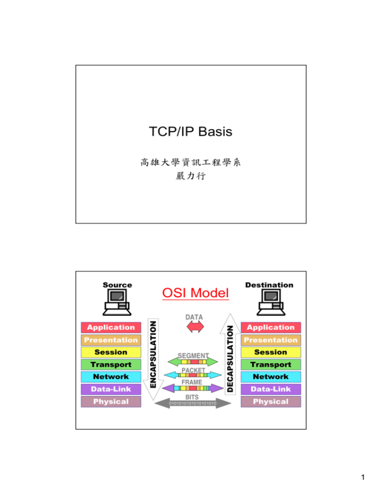
TCP/IP Basis OSI Model
advertisement
TCP/IP Basis 高雄大學資訊工程學系 嚴力行 Source OSI Model Destination Presentation Session Transport Network Data-Link Physical SEGMENT PACKET FRAME BITS 0101010101010101010 DECAPSULATION Application ENCAPSULATION DATA Application Presentation Session Transport Network Data-Link Physical 1 TCP/IP Model 涵蓋了OSI模型中的Application, Presentation, 和Session三層 Socket API TCP 或 UDP IP LAN, WAN 或其它網路 Application Layer Examples 2 IPv4 Addressing • An IP address is a 32-bit sequence of 1s and 0s. • To make the IP address easier to use, the address is usually written as four decimal numbers separated by periods. • This way of writing the address is called the dotted decimal format. IP Address Structure • Network number + Host number • Network numbers are assigned by the NIC (Network Information Center) to avoid conflicts. • All the hosts in a network (可以不透過 router而互相通訊的區域) must have the same network number. 3 IP Addresses: Self Identification Class 1 2 3 Range of host 01234567890123456789012345678901 addresses 1.0.0.0 to 127.255.255.255 A 0Network Host B 10 C 110 D 1110 Multicast address 224.0.0.0 to 239.255.255.255 E 11110 Reserved for future use 240.0.0.0 to 247.255.255.255 Network 128.0.0.0 to 191.255.255.255 Host Network Host 192.0.0.0 to 223.255.255.255 Classes of IP Network Addresses 4 Special IP Addresses All 1s mean “all”; All 0s mean “this” 00000000000000000000000000000000 This host netid A host on this network 00 00 Host 11111111111111111111111111111111 Network 127 Broadcast on the local network 11 11 Broadcast on a distant network (anything) Loopback Host Address vs. Network Address • Host address is assigned to a specific interface Network Host Host number cannot be all 0’s • Network address refers to a whole network – Not assigned to an interface Network 00 00 Host number is all 0’s For a k-bit host number, total 2k -2 addresses are assignable (excluding all 0’s and all 1’s) 5 One Host Address for One Host? • A host can have more than one interfaces • Each interface should be configured an independent host address 140.126.0.0 140.126.1.2 140.124.0.0 140.124.8.3 IP Addressing Problems • 32-bit IP address space is not enough • Organizing the address space by classes wastes millions of them – a class B address is far too large for most organizations • the routing table explosion – every router in the Internet would need a table with half a million entries, if that much class C networks are in use 6 Subnet Addressing •ack like a single network to the outside world •split into several parts for internal use Subnet 140.127.1.0 class B 140.127.0.0 140.127.1.1 140.127.1.2 140.127.2.1 140.127.2.2 G Subnet 140.127.2.0 Subnets A Class B Network IP address Subnet mask Network 11 Host Part Subnet 11 11 Host 11 00 00 • The standard does not restrict subnet masks to select contiguous bits of the address. 7 Introduction to Subnetting • Host bits must are reassigned (or “borrowed”) as network bits. • The starting point is always the leftmost host bit. 5 bits borrowed allows 25-2 or 30 subnets (sN 全為0或 的無法使用) 全為 或1的無法使用 的無法使用 Determining Subnet Mask Size Class C address 197.15.22.131 with a subnet mask of 255.255.255.224 (3 bits borrowed) 11000101 00001111 00010110 100 Network Field SN 00011 Host Field The address 197.15.22.131 would be on the subnet 197.15.22.128. 8 Establishing the Subnet Mask Address • Determines which part of an IP address is the network field and which part is the host field. • Follow these steps to determine the subnet mask: 1. Express the subnetwork IP address in binary form. 2. Replace the network and subnet portion of the address with all 1s. 3. Replace the host portion of the address with all 0s. 4. Convert the binary expression back to dotteddecimal notation. Subnet Mask Subnet mask in decimal = 255.255.240.0 = IP address / 20 9 Network Growth Problem • Problem – Immense administrative overhead • Every time a new network is installed the system administrator has to contact NIC to get a new network number. • Then this number must be announced worldwide. – Large routing table • Solution: To minimize network numbers by sharing one network number among multiple physical networks Classless InterDomain Routing (CIDR) • To solve the IP address depletion problem and the routing table explosion problem • RFC 1519 • The basic idea behind CIDR is to allocate the remaining class C networks in variable-sized (2x) blocks 10 Example • X University needs 2048 addresses and is assigned the addresses 194.24.0.0 through 194.24.7.255, along with mask 255.255.248.0. • Y University needs 4096 addresses and is assigned the addresses 194.24.16.0 through 194.24.31.255, along with mask 255.255.240.0. • Z University needs 1024 addresses and is assigned the addresses 194.24.8.0 through 194.24.11.255, along with mask 255.255.252.0. Example Routing table with entries 28 Class C networks base address 194.24.0.0 194.24.16.0 194.24.8.0 mask 255.255.248.0 255.255.240.0 255.255.252.0 248=(11111000)2 240=(11110000)2 252=(11111100)2 Destination address with 194.24.17.4 17=(00010001)2 Dest. IP & mask 194.24.17.4 & 255.255.248.0 = 194.24.16.0 194.24.17.4 & 255.255.240.0 = 194.24.16.0 ← match 194.24.17.4 & 255.255.252.0 = 194.24.16.0 11 Classless InterDomain Routing (CIDR) • The world was partitioned into zones, each given a portion of the class C address space: – – – – Addresses 194.0.0.0 to 195.255.255.255 for Europe Addresses 196.0.0.0 to 197.255.255.255 for Others Addresses 198.0.0.0 to 199.255.255.255 for North America Addresses 200.0.0.0 to 201.255.255.255 for Central and South America – Addresses 202.0.0.0 to 203.255.255.255 for Asia and Pacific – Addresses 204.0.0.0 to 207.255.255.255 for Others – Addresses 208.0.0.0 to 223.255.255.255 reserved for future use Internet Addressing: Host Names • • Mnemonic address made up of two parts: – Domain name • Assigned by a registrar • Example: aw.com • Top level domain: Classification of domain owner – By usage – Example: .com = commercial – By country – Example: .au = Australia – Subdomains and individual host names • Assigned by domain owner • Example: r2d2.compsci.nowhereu.edu Translation between mnemonic addresses and IP addresses handled by name servers (DNS server) 12 Public and Private IP Addresses • No two interfaces that connect to a public network can have the same IP address because public IP addresses are global and standardized. • However, private networks that are not connected to the Internet may use any host addresses, as long as each host within the private network is unique. Private Addresses and NAT • three blocks of IP addresses are set aside for private, internal use. Class A B C Private Address Range 10.0.0.0 to 10.255.255.255 172.16.0.0 to 172.16.255.255 192.168.0.0 to 192.168.255.255 • Connecting a network using private addresses to the Internet requires translation of the private addresses to public addresses using Network Address Translation (NAT). 13 NAT Translation Example NAT Router Internet Src = 192.168.1.2 Dst. = … Src = 218.168.153.6 Dst. = … Private Network NAT Router Internet Src. = … Dst. = 192.168.1.2 Src. = … Dst = 218.168.153.6 Dynamic Host Configuration Protocol (DHCP) • DHCP allows a host to obtain an IP address (public or private) using a defined range of IP addresses on a DHCP server. • As hosts come online, contact the DHCP server, and request an address. 14 DHCP與NAT在家庭網路的使用 4. PC1取得IP address的方式與Router相同 Private Network 192.168.1.1 PC1 PC2 Switch Router ADSL Modem To the Internet PC3 192.168.1.2 218.168.153.6 1. Router透過PPPoE建立與ISP的 link layer 並取得public IP address 2. Router啟動DHCP與NAT服務 3. PC3使用DHCP取得 private IP address IP分享器 Private Network Switch Router ADSL Modem To the Internet + DHCP + NAT IP分享器 15 無線IP分享器 Private Network Switch AP Router Modem To the Internet + DHCP + NAT 無線IP分享器 Transmission Control Protocol (TCP) • The protocols that use TCP include: – FTP (File Transfer Protocol) – HTTP (Hypertext Transfer Protocol) – SMTP (Simple Mail Transfer Protocol) – Telnet 16 UDP • The protocols that use UDP include: – TFTP (Trivial File Transfer Protocol) – SNMP (Simple Network Management Protocol) – DHCP (Dynamic Host Control Protocol) – DNS (Domain Name System) TCP and UDP Port Numbers • Both TCP and UDP use port (socket) numbers to pass information to the upper layers. – Numbers below 1024 are considered well-known ports numbers. – Numbers above 1024 are dynamically assigned ports numbers. – Registered port numbers are those registered for vendor-specific applications. Most of these are above 1024. 17 Some Well-Known Port Numbers IPv6: Introduction • The main problem of IPv4 is its relatively small address space • IPv6 extends IP address to 128 bits 18 IPv6 Address Hexadecimal Notation • Similar to IEEE 802 MAC addresses • Colon hexadecimal notation 805B:2D9D:DC28:0:0:FC57:D4C8:1FFF • Zero compression – Contiguous zeros are replaced by doubled colons (can appear only once) 805B:2D9D:DC28::FC57:D4C8:1FFF Two zero words here IPv6 Mixed Notation • IPv4 address can be embedded in an IPv6 address • It is useful to show the IPv4 portion of the address in dotted-decimal format 805B:2D9D:DC28::FC57:212.200.31.255 • 0:0:0:0:0:0:212.200.31.255 becomes ::212.200.31.255 19 IPv6/IPv4 Address Embedding • IPv4-compatible IPv6 addresses Special address assigned to IPv6-capable devices 0 32-Bit IPv4 Address 8 101 Used only for devices that are actually IPv6-aware IPv6 Address In Mixed Notation 64 0 32 219 96 00000000 00000000 00000000 00000000 00000000 00000000 00000000 00000000 00000000 00000000 0 75 便於轉換成IPv4位址 32 Prefix IPv4 Address With 80 Zero Bit 24 16 45 0 0 128 00000000 00000000 101 45 75 219 0 101 45 75 219 0 ::101.45.75.219 Compressed IPv6 Address IPv6/IPv4 Address Embedding • IPv4-mapped IPv6 addresses Regular IPv4 addresses that have been mapped into IPv6 address space 0 32-Bit IPv4 Address 8 222 1 For devices that are not IPv6-capable IPv6 Address In Mixed Notation 64 Compressed IPv6 Address 0 90 96 00000000 00000000 00000000 00000000 00000000 00000000 00000000 00000000 00000000 00000000 0 41 32 由IPv4位址轉換來的 32 Prefix IPv4 Address With 64 Zero Bit and 14 One Bit 24 16 0 0 128 11111111 11111111 222 1 41 90 FFFF 222 1 41 90 0 ::FFFF:101.45.75.219 20 IPv6 Address Prefix Length Representation • IPv6 addresses are divided into a number of network ID bits followed by a number of host ID bits • The network identifier is called the prefix, and the number of bits used is prefix length • The prefix is represented by adding a slash after the address and then putting the prefix length after the slash 805B:2D9D:DC28::FC57:D4C8:1FFF / 48 21
