Chiller-Plant Control Using Gateway Technologies
advertisement
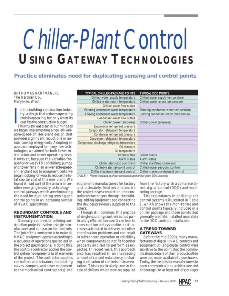
Chiller-Plant Control USING GATEWAY TECHNOLOGIES Practice eliminates need for duplicating sensing and control points By THOMAS HARTMAN, PE, The Hartman Co., Marysville, Wash. I n the building-construction industry, a design that reduces operating costs is appealing, but only when its cost fits the construction budget. This truism was clear in our minds as we began implementing a new all-variable-speed-chiller-plant design that provides significant reductions in annual cooling-energy costs. Adopting an approach employed for many new technologies, we aimed for both lower installation and lower operating costs. However, because the variable-frequency drives (VFD) of chillers, pumps, and tower fans in an all-variable-speedchiller plant add to equipment costs, we began looking for ways to reduce the total capital cost of this new plant. We found at least part of the answer in another emerging industry technology— control gateways, which are eliminating the need for duplicating sensing and control points in an increasing number of HVAC applications. REDUNDANT CONTROLS AND INSTRUMENTATION Generally, commercial-building construction projects involve a single manufacturer and contractor for controls. The job of this contractor is to make all HVAC equipment operate according to a sequence of operations spelled out in the project specifications. In doing this, the controls contractor applies the control system he represents to all elements of the project. The contractor supplies controllers and actuators, modulating valves, dampers, and other equipment to the mechanical contractor(s) and TYPICAL CHILLER-PACKAGE POINTS Chilled-water supply temperature Chilled-water return temperature Chilled-water flow status Entering condenser-water temperature Leaving condenser-water temperature Condenser-water flow status Chiller power (amperes) Evaporator refrigerant pressure Evaporator refrigerant temperature Condenser refrigerant pressure Condenser refrigerant temperature Compressor discharge refrigerant temperature Oil pressure Oil temperature Chiller status Alarm status Chiller start/stop command Chilled-water set-point control Chiller maximum-demand control TYPICAL DDC POINTS Chilled-water supply temperature Chilled-water return temperature Entering condenser-water temperature Leaving condenser-water temperature Chiller power (amperes) Chiller status Alarm status Chiller start/stop command Chilled-water set-point control Chiller maximum-demand control TABLE 1. Points included in chiller controllers and chiller-plant DDC controls. equipment manufacturers for factory and, ultimately, field installation. As the project nears completion, the controls contractor goes through the building, adding equipment and connecting the devices previously supplied to the others. Though still common, this practice of single-sourcing controls is not particularly efficient because it can lead to construction delays and/or cost increases attributed to delivery and other coordination problems and can result in substandard operation or reliability when components do not fit together properly and fail to perform as expected. In recent years, this approach also has resulted in an increasing amount of control redundancy, including duplication of controls instrumentation. This is particularly true in the case of chillers, which now are supplied from the factory with a complete direct-digital-control (DDC) and monitoring package. The redundancy in chiller-plant control systems is illustrated in Table 1, which shows the monitoring and control points typically included in a chiller package and those points that generally are field-installed separately in the DDC controls installation. A TREND TOWARD GATEWAYS Before the mid-1990s, many manufacturers of digital HVAC controls and equipment utilizing digital control were secretive to the point that the communications details of their products often were not made available to purchasers. Today, the trend is for manufacturers to open communications architecture and encourage (or at least not discourage) Heating/Piping/AirConditioning • January 2000 HPAC ENGINEERING 81 CONTROL GATEWAYS others to communicate with their systems through published interface information using communication “gateways.” Many manufacturers of HVAC controls and equipment have an in-house interface standard that can be employed by others for connection to and communication with their equipment, while others are embracing one or more of the emerging industry communication protocol standards. Currently, the primary method of connecting different systems involves gateway-type connections, but in the future, systems may employ industry-standard architecture throughout or have gateways embedded in all controllers so that connection to other systems can be made throughout their network architecture. The result of this trend is that controls and equipment from different manufacturers usually can be connected and interoperated to some degree. This development is being embraced because: n Manufacturers of equipment such as air handlers, cooling towers, and VAV boxes, who typically either have shipped components without controls or had to factory-install controls and devices supplied by others, realize that designing their equipment around their own controls and devices enables them to better control manufacturing costs, streamline production, and capture more value. n Design engineers realize that it may simplify and speed the construction process and help them satisfy their clients’ desire not to be tied to a single controlsystem vendor. n Building owners and managers believe that it will facilitate integration with other building and computing sys- What Is a ‘Gateway’? any digital systems used in building operation today employ rules for communicating among their units that are unique to their system. That is why even when two different systems employ the same RS485 or Ethernet local-areanetwork architecture, it usually still is not possible for them to exchange information. Only when both systems also employ the same communication protocol, such as BACnetE or LonWorks, can intercommunication be counted upon. For systems that do not employ the same network architecture and communication rules, a “gateway” (sometimes called “protocol interface”) is required. A communication gateway is a device that connects two networks and converts dissimilar protocols. Some gateways employed in large wide-area-network and Internet applications are complex and expensive, but those required for direct-digital-control (DDC) systems usually are quite simple. Typical communication gateways consist of three elements: ● A communication link that connects the two (or more) systems. ● One or more translators (or drivers) that understand the communication rules of each system being connected so that data streams can be converted into useful information for the system or systems that require the interconnection. ● A simple operating system and section of memory (or buffer) where required intercommunication data is mapped so that relevant data is captured and stored until it can be communicated to the other system(s). Today, most DDC field panels are built with gateways. Gateways enable simple variable-air-volume terminal-control networks to communicate on a higher-speed field-panel communications network. Many such panels also include configurable gateways. Depending on the requirement for intercommunication, such control panels can be shipped from the factory with the communications link and drivers required for intercommunication or these features can be field-installed and programmed. Thus, the cost of gateway integration of systems has fallen dramatically in recent years and can be expected to approach zero for common systems in the near future. Many in the industry see gateways as a temporary fix as the move toward standard communication protocols takes place. However, whether the entire building-construction industry ever will embrace a single communication standard remains an open question. M 82 HPAC ENGINEERING January 2000 • Heating/Piping/AirConditioning tems and improve the “enterprise”-level performance of their facility-management system with features that reach far beyond the simple HVAC monitoring and control that is the limit of most building-control systems. GATEWAYS FOR CHILLERS AND VARIABLE-FREQUENCY DRIVES As the trend toward gateways developed, the first two types of equipment to become available with gateway-type communication interfaces were chillers and VFDs. For this reason, an all-variable-speed-chiller plant is an excellent starting point for employing this new approach. A comparison of a standard chillerplant DDC connection and a DDC interface with a gateway-type connection can be made by considering figures 1 and 2. Figure 1 shows how a conventional chiller plant that employs constant-speed chillers, pumps, and fans typically would be instrumented using discrete devices for each DDC I/O point. The power- and flow-metering equipment is included to provide chilled-water production and plant-efficiency information to the owner and operations staff. The DDC interface shown in Figure 1 requires 45 separate points. An all-variable-speed plant would be expected to have the same or even a larger number of discrete points, because each VFD must be operated both digitally (start/stop) and via analog control (motor speed). However, by employing a gateway approach as diagrammed in Figure 2, the number of discretely connected points required in an all-variablespeed-plant design is reduced to nine. All other input and output points are connected through the networks. This large reduction in discrete hardware connections is made possible by several networking and interconnecting features of VFDs. Note that the VFD operating the chiller compressors in Figure 1 are connected to the chiller controller, but in the connection scheme of Figure 2, each also is connected to the chiller-plant network. Depending on the chiller connection to the VFD, this is useful because it makes information accessible via a net- CT1 SS DO Relay CT1 STS DI Current switch CT1 KW AI kw transducer DO kw CT2 SS Relay DI CT2 STS Current switch AI CT2 KW kw transducer kw C CT1 ALRM DI Dry contact CT1 HTR DO Relay CT1 STEMP AI C DI CT2 ALRM Dry contact DO CT2 HTR Relay AI CT2 STEMP Wtr temp sensor Wtr temp sensor CDWP1 SS DO Relay CDWP1STS DI Current switch CDWP1 KW AI kw transducer C DO CDWP2 SS Relay DI CDWP2STS Current switch AI CDWP2 KW kw transducer C kw kw AI CH1 ECDWT Wtr temp sensor AI CH1ECDWT AI CH2ECDWT Wtr temp sensor Wtr temp sensor DO CH1 SS Relay DI CH1 Dry contact AO CH1CWTSP 4-20ma signal AO CH1DMDSP 4-20ma signal Al CH1 KW kw transducer AI CH2 ECDWT DO CH2 SS Relay DI CH2 Dry contact AO CH2CWTSP 4-20ma signal AO CH2DMDSP 4-20ma signal AI CH2 KW kw transducer Wtr temp sensor COND COND EVAP kw Chiller 1 PCWP1 SS DO Relay PCWP1STS DI Current switch PCWP1 KW AI kw transducer COND AI CH1 SCWT AI CH2 SCWT Wtr temp sensor Wtr temp sensor AI CH1 RCWT AI CH2 RCWT Wtr temp sensor Wtr temp sensor EVAP kw Chiller 2 C C kw kw AI CWFLOW Flow meter AI SCWT Wtr temp sensor AI COMP RCWT Wtr temp sensor DO PCWP2 SS Relay DI PCWP2STS Current switch AI PCWP2 KW kw transducer Point type DI — Digital input DO — Digital output AI — Analog input AO — Analog output Point name DO CT2 HTR Relay Chilled-water supply and return to and from the distribution system I/O device DDC Ppoint Legend FIGURE 1. Conventional constant-speed-chiller-plant DDC interface. work connection that otherwise would not be accessible through the chiller controller. While such a dual-network connection may be unusual, it will not compromise effective chiller operation because all operating commands to the VFD still would be coordinated through the chiller controls. The network connection to the VFD may be used to report only the power ( KW ) draw of the chiller. With pump and fan VFD, the network connection is used to turn the VFD on and off, set its speed, determine its status, and read the instanta- neous KW use of the motor controlled by the VFD. The points that are communicated to the chiller-plant controller by the network are shown in Table 2. We estimate that the reduction in devices and field work attributed to these network connections will cut controls costs by 25 to 30 percent, which is sufficient to pay the premium for VFD for all fans and pumps in the plant. With this network-based control scheme and other economies, it is possible to implement all-variablespeed-chiller plants that cost the same as or less than and that significantly outperform conventional high-efficiency constant-speed-chiller plants. PITFALLS OF GATEWAY CONNECTIONS However, before implementing a controls design that employs gateways, a designer should be aware of the common pitfalls of gateway connections and take steps to avoid them. The three most common problems with gateway connections we have seen are: n Information is not accessible across the network as desired. A commandable point such as a digital output Heating/Piping/AirConditioning • January 2000 HPAC ENGINEERING 83 CONTROL GATEWAYS (DO) or analog output (AO) may be unable to receive a command across the network because operating capabilities across gateways usually are limited by equipment manufacturers—unless, that is, requirements are specified clearly. n Timing and precision issues across the network hamper smooth operation. The network interface may be so slow that information exchanges take minutes to perform or a gateway may have such a large change-of-value (COV) limit that an analog input (AI) must change significantly before the change will be reported across the network. Both of these limitations may make cross-network control unstable or erratic if timing and COV reportinglimit requirements are not made clear in the specifications. n Point value or status becomes unstable under certain conditions. If a point value exceeds the range that is expected by the gateway or if commu- VFD nication across the network is lost, the receiving controller may not retain a default value or status. The designer must be certain that these possibilities have been carefully considered and dealt with effectively to ensure the operational integrity of a network-based control system. These potential problems and others that can crop up easily make it imperative that a designer use great care when employing gateway data-transfer de- VFD CT1 ALRM DI Dry contact CT1 HTR DO Relay CT1 STEMP AI DI CT2 ALRM Dry contact DO CT2 HTR Relay AI CT2 STEMP Wtr temp sensor Wtr temp sensor VFD VFD Network connection Network connection Network connection Network connection COND COND Network connection Network connection VFD COND COND EVAP EVAP VFD Chiller 2 Chiller 1 Network connection Network connection VFD VFD Point type DI — Digital input DO — Digital output AI — Analog input AO — Analog output AI CWFLOW Flow meter SCWT AI Wtr temp sensor AI RCWT Point name AI Wtr temp sensor RCWT Wtr temp sensor I/O device DDC Point Legend Chilled-water supply and return to and from the distribution system FIGURE 2. All-variable-speed-chiller-plant DDC interface using network connections to chillers and variable-speed drives. 84 HPAC ENGINEERING January 2000 • Heating/Piping/AirConditioning C H I L L E R - P L A N T - N E T W O R K Description Point name System Bldg System Point Chiller plant — networked points schedule Chiller No. 1 control panel Chilled-water supply temp CP CH1 CWST Chilled-water return temp CP CH1 CWRT Chilled-water flow status CP CH1 CWFLO Entering condenser-water temp CP CH1 ECDWT Leaving condenser-water temp CP CH1 LCDWT Condenser-water flow status CP CH1 CDWFLO Evaporator refrigerant pressure CP CH1 EVAPP Evaporator refrigerant temp CP CH1 EVAPT Condenser refrigerant pressure CP CH1 CDNP Condenser refrigerant temp CP CH1 CDNT Compressor-discharge temp CP CH1 DISCHT Inlet vane position signal CP CH1 VANE Oil pressure CP CH1 OILP Oil temperature CP CH1 OILT Chiller status CP CH1 Alarm status CP CH1 ALRM Chiller start/stop command CP CH1 SSC Chilled-water set-point control CP CH1 CWSPC Chiller-demand control CP CH1 DMDC Chiller No. 1 variable-frequency drive VFD compressor speed signal CP CH1D RPM VFD status CP CH1D VFD alarm CP CH1D ALRM VFD power CP CH1D KW Chiller No. 1 CW pump variable-frequency drive VFD pump speed command signal CP CWP1 RPMC VFD status CP CWP1 VFD alarm CP CWP1 ALRM VFD power CP CWP1 KW Chiller No. 1 CDW pump variable-frequency drive VFD pump speed command signal CP CDWP1 RPMC VFD status CP CDWP1 VFD alarm CP CDWP1 ALRM VFD power CP CDWP1 KW Chiller No. 1 tower-fan variable-frequency drive VFD fan speed command signal CP CT1F RPMC VFD status CP CT1F VFD alarm CP CT1F ALRM VFD power CP CT1F KW Chiller No. 2 control panel Chilled-water supply temp CP CH2 CWST Chilled-water return temp CP CH2 CWRT Chilled-water flow status CP CH2 CWFLO Entering condenser-water temp CP CH2 ECDWT Leaving condenser-water temp CP CH2 LCDWT Condenser-water flow status CP CH2 CDWFLO Evaporator refrigerant pressure CP CH2 EVAPP Evaporator refrigerant temp CP CH2 EVAPT Condenser refrigerant pressure CP CH2 CDNP Condenser refrigerant temp CP CH2 CDNT Compressor discharge temp CP CH2 DISCHT Inlet vane position signal CP CH2 VANE Oil pressure CP CH2 OILP Oil temperature CP CH2 OILT Chiller status CP CH2 Alarm status CP CH2 ALRM Chiller start/stop command CP CH2 SSC Chilled-water set-point control CP CH2 CWSPC Chiller demand control CP CH2 DMDC Chiller No. 2 variable-frequency drive VFD compressor speed signal CP CH2D RPM VFD status CP CH2D VFD alarm CP CH2D ALRM VFD power CP CH2D KW Chiller No. 2 CW pump variable-frequency drive VFD pump speed command signal CP CWP2 RPMC VFD status CP CWP2 VFD alarm CP CWP2 ALRM VFD power CP CWP2 KW Chiller No. 2 CDW pump variable-frequency drive VFD pump-speed command signal CP CDWP2 RPMC VFD status CP CDWP2 VFD alarm CP CDWP2 ALRM VFD power CP CDWP2 KW Chiller No. 2 tower-fan variable-frequency drive VFD fan speed command signal CP CT2F RPMC VFD status CP CT2F VFD alarm CP CT2F ALRM VFD power CP CT2F KW Type Range AI AI DI AI AI DI AI AI AI AI AI AI AI AI DI DI DO AO AO 20F - 70F 20F - 70F Yes/No 50F - 120F 50F - 120F Yes/No See comment. 20F - 70F See comment. 20F - 70F 50F - 120F 0% - 100% 0-50 psi 50F - 160F On/Off Alarm/Off Start/Stop 38F - 54F 10% - 100% AI DI DI AI 0% - 100% On/Off Alarm/Off See comment. AO DI DI AI 0% - 100% On/Off Alarm/Off See comment. AO DI DI AI 0% - 100% On/Off Alarm/Off See comment. AO DI DI AI 0% - 100% On/Off Alarm/Off See comment. AI AI DI AI AI DI AI AI AI AI AI AI AI AI DI DI DO AO AO 20F - 70F 20F - 70F Yes/No 50F - 120F 50F - 120F Yes/No See comment. 20F -70F See comment. 20F -70F 50F - 120F 0% - 100% 0-50 psi 50F - 160F On/Off Alarm/Off Start/Stop 38F - 54F 10% -100% AI DI DI AI 0% - 100% On/Off Alarm/Off See comment. AO DI DI AI 0% - 100% On/Off Alarm/Off See comment. AO DI DI AI 0% - 100% On/Off Alarm/Off See comment. AO DI DI AI 0% - 100% On/Off Alarm/Off See comment. HPAC ENGINEERING L I S T Connect via specified interface between chiller controls and chiller-plant controller. Range is minimum. Scale point as required depending on operating pressure of refrigerant employed in chiller. Scale point as required depending on operating pressure of refrigerant employed in chiller. Connect via specified interface between VFD network and chiller-plant controller. Connect to provide 0- to 100-percent outside-air damper control. Actuator by AHU mfg. Scale point as required depending on operating power range of unit. Connect via specified interface between VFD network and chiller-plant controller. Scale point as required depending on operating power range of unit. Connect via specified interface between VFD network and chiller-plant controller. Scale point as required depending on operating power range of unit. Connect via specified interface between VFD network and chiller-plant controller. Scale point as required depending on operating power range of unit. Connect via specified interface between chiller controls and chiller-plant controller. Range is minimum. Scale point as required depending on operating pressure of refrigerant employed in chiller. Scale point as required depending on operating pressure of refrigerant employed in chiller. Connect via specified interface between VFD network and chiller-plant controller. TABLE 2: Networked all-variable-speed-chiller-plant DDC points. 86 P O I N T S Comments January 2000 • Heating/Piping/AirConditioning Scale point as required depending on operating power range of unit. Connect via specified interface between VFD network and chiller-plant controller. Scale point as required depending on operating power range of unit. Connect via specified interface between VFD network and chiller-plant controller. Scale point as required depending on operating power range of unit. Connect via specified interface between VFD network and chiller-plant controller. Scale point as required depending on operating power range of unit. CONTROL GATEWAYS sign schemes. While there is a developing consensus about how gateway interfaces should perform, individual opinions vary widely at this early stage, with some manufacturers new to the idea of cross-network operations. This can lead to misunderstandings about the role of each gateway and result in unsatisfactory performance of systems that rely on gateway communication. To minimize such problems, I recommend that special consideration be given to specifying each gateway connection or interface. SPECIFYING GATEWAYS While much has been written about how to specify interfaces between systems, much more needs to be developed. My rule for myself is never specify features I do not fully understand or that are too difficult to evaluate to be enforced. To ensure an effective interface, our firm believes one should: n Base the gateway or interface specification on a well-known industry standard. We recommend never basing an interface specification on a single company’s “open” standard. Instead, we specify at least one industrystandard communication-interface option. However, after all of the equipment and systems have been selected, it may be useful to entertain proposals for an inter-system interface employing a non-standard “open” interface. Such a proposal could be accepted if it results in reduced costs, it comes with a guarantee that the operational capabilities will not be compromised, and the owner agrees that such change will not limit the ability to implement desired upgrades. n Describe exactly what data need to be transferred across the interface and how that data is to be employed by each system involved. For example, if a chiller must be controlled on and off and have its maximum power setting set across a gateway interface, it is necessary to call for the chiller start/stop and demand-control points to be networked across the gateway. It also is necessary to explain how and where in the network the commands are to be made. Finally, it is useful to detail how the information will be employed on each side of the interface, how often data must be sent and/or received, and any other information that helps ensure that the system operates effectively. n Assign a single source of responsibility and authority in making each interface work. From chiller and VFD interfaces to DDC controls, we recommend that the DDC-controls vendor be responsible for each interface and be given the authority to determine if the interfaces provided by the chiller or VFD vendor meet the requirements of the specified interface standard and other specification items. If the controls vendor concludes that an interface does not meet specified requirements, then the provider of that interface must make the changes mandated by the controls vendor or clearly show where the controls vendor erred. This approach greatly reduces the finger pointing that can overwhelm a designer when a multi-vendor network is brought on-line. By basing gateway connections on industry-standard communications, fully specifying the data that must be transferred and how it is to be transferred, and assigning a single point of authority and responsibility for the interconnections, confusion and finger pointing during installation and startup is minimized. This approach is a good model for designers approaching a future in which multi-vendor controls networks likely will become standard practice. GATEWAYS: CHANGING HVAC CONTROLS FOREVER As the trend toward gateways and other interface standards is accelerated by the increasing demands and expectations of major industry players, I believe that the way our industry works will change forever. Controls contractors increasingly will work to fill a serious void in construction services and increase their sales by recasting themselves as “system integrators.” As part of this changing role, they will lose their loyalty to the control-system manufacturer to which they historically were bound and start looking to expand their product line and their knowledge of other systems so that they will be able to offer the most at- tractive combination of hardware products and capture a larger piece of the growing equipment and data-integration market. Manufacturers of control products will begin to find the construction market for their products shrinking, as more and more controls are factory-installed under OEM agreements. Contractors will find the construction process to be simpler and startup easier—but only if designers have done their job well. The design stage, therefore, will become more important and require designers to develop digitalcommunication expertise that is not widely available in the industry today. But if designers are successful in developing this expertise and employing it in well-structured controls specifications, then putting together an HVAC system will, from the standpoint of controls, become more like putting together an office data-communications network. It will be easier and less costly than controls implementation is today and result in a better-performing system. SUMMARY AND CONCLUSION Employing gateways to connect systems effectively requires substantial adjustments to the design and specification of affected systems. However, the results are worth the effort, as construction costs and startup problems are reduced through the elimination of point redundancy. Because manufacturers of chillers and VFD are leaders in the trend toward gateway connection, employing gateways to connect their equipment to DDC systems offers a good opportunity for designers to begin employing this important new technology and prepare for a future in which multivendor control systems will be common. Additional information on technologies discussed in this article is available on the Web at www.hartmanco.com. Questions and comments about the article can be addressed to the author at HPAC tomh@hartmanco.com. Circle 502 on reader service card if this article was useful; circle 503 if it was not. Heating/Piping/AirConditioning Heating/Piping/AirConditioning • January • Month2000 Year HPAC ENGINEERING 876
