Design and Simulation of 8255 Programmable Peripheral Interface
advertisement
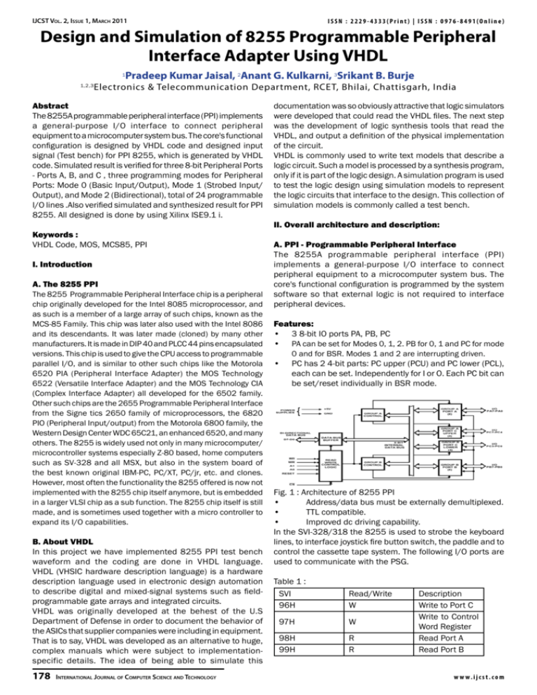
IJCST Vol. 2, Issue 1, March 2011 ISSN : 2229-4333(Print) | ISSN : 0976-8491(Online) Design and Simulation of 8255 Programmable Peripheral Interface Adapter Using VHDL 1 1,2,3 Pradeep Kumar Jaisal, 2Anant G. Kulkarni, 3Srikant B. Burje Electronics & Telecommunication Department, RCET, Bhilai, Chattisgarh, India Abstract The 8255A programmable peripheral interface (PPI) implements a general-purpose I/O interface to connect peripheral equipment to a microcomputer system bus. The core's functional configuration is designed by VHDL code and designed input signal (Test bench) for PPI 8255, which is generated by VHDL code. Simulated result is verified for three 8-bit Peripheral Ports - Ports A, B, and C , three programming modes for Peripheral Ports: Mode 0 (Basic Input/Output), Mode 1 (Strobed Input/ Output), and Mode 2 (Bidirectional), total of 24 programmable I/O lines .Also verified simulated and synthesized result for PPI 8255. All designed is done by using Xilinx ISE9.1 i. Keywords : VHDL Code, MOS, MCS85, PPI I. Introduction A. The 8255 PPI The 8255 Programmable Peripheral Interface chip is a peripheral chip originally developed for the Intel 8085 microprocessor, and as such is a member of a large array of such chips, known as the MCS-85 Family. This chip was later also used with the Intel 8086 and its descendants. It was later made (cloned) by many other manufacturers. It is made in DIP 40 and PLCC 44 pins encapsulated versions. This chip is used to give the CPU access to programmable parallel I/O, and is similar to other such chips like the Motorola 6520 PIA (Peripheral Interface Adapter) the MOS Technology 6522 (Versatile Interface Adapter) and the MOS Technology CIA (Complex Interface Adapter) all developed for the 6502 family. Other such chips are the 2655 Programmable Peripheral Interface from the Signe tics 2650 family of microprocessors, the 6820 PIO (Peripheral Input/output) from the Motorola 6800 family, the Western Design Center WDC 65C21, an enhanced 6520, and many others. The 8255 is widely used not only in many microcomputer/ microcontroller systems especially Z-80 based, home computers such as SV-328 and all MSX, but also in the system board of the best known original IBM-PC, PC/XT, PC/jr, etc. and clones. However, most often the functionality the 8255 offered is now not implemented with the 8255 chip itself anymore, but is embedded in a larger VLSI chip as a sub function. The 8255 chip itself is still made, and is sometimes used together with a micro controller to expand its I/O capabilities. B. About VHDL In this project we have implemented 8255 PPI test bench waveform and the coding are done in VHDL language. VHDL (VHSIC hardware description language) is a hardware description language used in electronic design automation to describe digital and mixed-signal systems such as fieldprogrammable gate arrays and integrated circuits. VHDL was originally developed at the behest of the U.S Department of Defense in order to document the behavior of the ASICs that supplier companies were including in equipment. That is to say, VHDL was developed as an alternative to huge, complex manuals which were subject to implementationspecific details. The idea of being able to simulate this 178 International Journal of Computer Science and Technology documentation was so obviously attractive that logic simulators were developed that could read the VHDL files. The next step was the development of logic synthesis tools that read the VHDL, and output a definition of the physical implementation of the circuit. VHDL is commonly used to write text models that describe a logic circuit. Such a model is processed by a synthesis program, only if it is part of the logic design. A simulation program is used to test the logic design using simulation models to represent the logic circuits that interface to the design. This collection of simulation models is commonly called a test bench. II. Overall architecture and description: A. PPI - Programmable Peripheral Interface The 8255A programmable peripheral interface (PPI) implements a general-purpose I/O interface to connect peripheral equipment to a microcomputer system bus. The core's functional configuration is programmed by the system software so that external logic is not required to interface peripheral devices. Features: • 3 8-bit IO ports PA, PB, PC • PA can be set for Modes 0, 1, 2. PB for 0, 1 and PC for mode • 0 and for BSR. Modes 1 and 2 are interrupting driven. PC has 2 4-bit parts: PC upper (PCU) and PC lower (PCL), each can be set. Independently for I or O. Each PC bit can be set/reset individually in BSR mode. Fig. 1 : Architecture of 8255 PPI • Address/data bus must be externally demultiplexed. • TTL compatible. • Improved dc driving capability. In the SVI-328/318 the 8255 is used to strobe the keyboard lines, to interface joystick fire button switch, the paddle and to control the cassette tape system. The following I/O ports are used to communicate with the PSG. Table 1 : SVI 96H Read/Write W 97H W 98H 99H R R Description Write to Port C Write to Control Word Register Read Port A Read Port B w w w. i j c s t. c o m ISSN : 2229-4333(Print) | ISSN : 0976-8491(Online) IJCST Vol. 2, Issue 1, March 2011 we required some power supply to start the 8255 PPI Chip doing operation, in this Project we need 5V supply to trigger or start the 8255 chip. Fig. 2 : Pin diagram of 8255 PPI The IC used for interfacing is the 8255 PPI. This chip is designed and manufactured by Intel. The 8255 Interface Adapter is a programmable peripheral interface device designed for use in microcomputer interfacing systems. It is a general purpose I/O device that can interface any TTL compatible peripheral device to a microcomputer system. The 8255 has 24 pins of I/O, programmable and configurable by software, in two groups of 12 pins that are used in three separate modes of operation (Brey, 1995). The Interface Adapter is selected by its CS line for programming and for reading and writing to a port. Port assignment and register selection is accomplished through the A1 and A0 pins. Table 2 shows the I/O port assignments used programming and access the I/O ports (Rafiquzzaman, 1995; Uffenbeck, 1998). Table 2 : Function of Port A, B, C and CWR B. Programming with 8255 PPI The 8255 has 3 8-bit ports (A, B and C), each of which can have a different I/O Status (i.e. input or output). Port C can also be programmed to operate in two halves. (As two separate 4-bit ports). The functional configuration of each port is programmed but the system software. In essence, the CPU "outputs" a control word to the 8255. The control word contains information such as "mode", "bit set", "bit reset", etc, that initializes the functional configuration of the 8255. There are 3 basic modes of operation under which the ports can function. Mode 0 - Basic Input/ output Mode 1 - Strobed Input/output (Not used by SVI) Mode 2 - Bi-Directional Bus (Not used by SVI) in some of these modes port C is used as a control/status port for port A or B. It can be used to confirm when data transfer may take place, and reflect any other flags. The 8255 PPI is therefore supplied with the added option for the user to set or reset any individual bits in port C. The I/O status, mode of operation and bit setting is defined by the 8255 PPI control byte. (The control byte is accessed using port 97H, 8255 Control port) The ports may be accessed separately by the CPU. Port A is accessed using port 98H, Port B is accessed using port 99H, Port C is accessed using port 96H. D. Use 8255 PPI in VHDL programming 8255 PPI is used in VHDL; we use VHDL code as in input and to give the output in simulated test bench waveform. As we know that, this is also perform in the matlab and P-spice technology and in this project we are using new advance technology called VHDL to give simulated test bench waveform of 8255 PPI. The codes for the different modules are written in VHDL and are simulated using Xilinx ISE 9.1i. E. Results obtained: 1. RTL View of 8255 PPI Architecture Fig. 3: RTL View of 8255 PPI Architecture 2. RTL View of 8255 PPI Core Internal Fig. 4: RTL View of 8255 PPI Core Internal Architecture 3. RTL View of 8255 PPI Core Architectur Fig. 5: RTL View of 8255 PPI Core Architecture C. Adapter 8255 PPI Adapter is called Vcc as a pull up Architecture to use this project, at any circuit or chip having some supply as required to start the circuit. Adapter are used in 8255 PPI using VHDL, w w w. i j c s t. c o m International Journal of Computer Science and Technology 179 IJCST Vol. 2, Issue 1, March 2011 4. RTL View of 8255 PPI Core Internal Architecture ISSN : 2229-4333(Print) | ISSN : 0976-8491(Online) 2. Simulated Test Bench waveform Fig. 6 : RTL View of 8255 PPI Core Internal Architecture 5. RTL View of 8255 PPI Core Internal Architecture Fig. 10 : Simulated Test bench Waveform 8255 PPI Architecture 3. Simulated Test Bench waveform Fig. 7: RTL View of 8255 PPI Core Internal Architecture 6. RTL View of 8255 PPI Core Internal Architecture Fig. 8: RTL View of 8255 PPI Core Internal Architecture Fig. 11: Simulated Test bench Waveform 8255 PPI Architecture 1. Simulated Test Bench waveform 4. Simulated Test Bench waveform Fig. 12: Simulated Test bench Waveform 8255 PPI Architecture Fig. 9: Simulated Test bench Waveform 8255 PPI Architecture V. Conclusion As the application of microprocessors in our technology intensive environment increases, so does the need for professionals who are able to utilize, control, interconnect, and troubleshoot 180 International Journal of Computer Science and Technology w w w. i j c s t. c o m ISSN : 2229-4333(Print) | ISSN : 0976-8491(Online) IJCST Vol. 2, Issue 1, March 2011 computers. In order to meet the demands of computer-based organizations, students pursuing an engineering technology degree program in electronics should develop practical skills in the areas of computer applications, networking, and interfacing. The knowledge of interfacing technology, indeed, enhances the employability skills of engineering technology students. This project 8255 PPI using VHDL Based upon Simulated Test bench waveform analysis. A test bench is used to verify the functionality of a design. The test bench allows the design to verify the functionality of the design at each step in the HDL synthesis-based methodology. When the designer makes a small change to fix an error, the change can be tested to make sure that it did not affect other parts of the design. New versions of the design can be verified against known good results to verify compatibility. 8255 PPI is designed in this methodology and simulated all the functions .Simulated waveform is analysis and give the output of Behavioral structure of 8255 PPI. References [1] Harris Semiconductor, “CMOS Programmable Peripheral Interface”, Product Specification, June 1998. [2] Paul, “8255 PPI IBM PC Interface Card”, Tutorial, Nov 2000. [3] Intel, “Programmable Peripheral Interface”, Data Sheet, 1999. [4] T.C. Manjunath, S. Janardhanan, N.S. Kubal, “Simulation, Design, Implementation and Control of a Welding Process Using Micro – controller”, Paper presentation at Institute of Technology Bombay, Powai, Mumbai. [5] Pradeep Kumar Jaisal, Anant G. Kulkarni, “Design of Time Triggered Shared Bus Architecture Using Very High Speed Integrated Circuit Hardware Description Language (VHDL)”, Paper Published at International Journal of Electronics and Computers, Vol. 2, No. 2, pp. 353-364. w w w. i j c s t. c o m International Journal of Computer Science and Technology 181
