Testing Residential
Cabling Systems
Installers and contractors who will install
A hundred years ago, it was
this new cabling need to learn new skills and
unheard of to run wires through
information because data cabling installation
the walls of your home for tele-
is similar, but markedly different from the
phones. 50 years later, telephone
wiring was commonplace, but
people would scoff at the idea
of television wiring in the home.
practices used to install telephone wiring.
In fact, even telephony wiring is changing.
Many newer systems employ the same 4-pair
UTP cabling used in data networks.
Residential data communications cabling
Today, all homes come standard
is typically 4-pair, 100-ohm twisted pair
with both telephone and TV
cabling rated at Category 5 or 5E. It runs
cabling pre-installed. What about
from the Network Interface Device (or NID,
the future? The next anticipated
a wiring distribution panel, located near the
trend is structured communica-
outside data access connection) to outlets
tions cabling for home computer
positioned in rooms throughout the home.
networks. In the near future,
homes will have multiple comput-
The homeowner may choose to connect a
hub at the NID, or simply connect directly to
the outside Internet access service, depend-
ers, printers, scanner, and fax –
ing upon the desired complexity of the home
all connected to the Internet via
network.
a single high-speed connection.
When installing residential cabling, care
Homeowners will expect pre-wired
must be taken to preserve proper twist ratios
jacks for computer networks
in the cable when attaching data jacks, in
alongside telephone and cable TV
outlets.
Already, much work is being
order to minimize crosstalk concerns. To
avoid deformation, the cable also should not
be stretched or pulled around sharp corners,
which could lead to performance degrada-
done to standardize requirements
tion. When possible, data cabling should be
for home cabling, often called
routed away from cables carrying AC power
SOHO (Small Office Home Office)
to avoid noise coupling.
cabling. In the U.S., this is
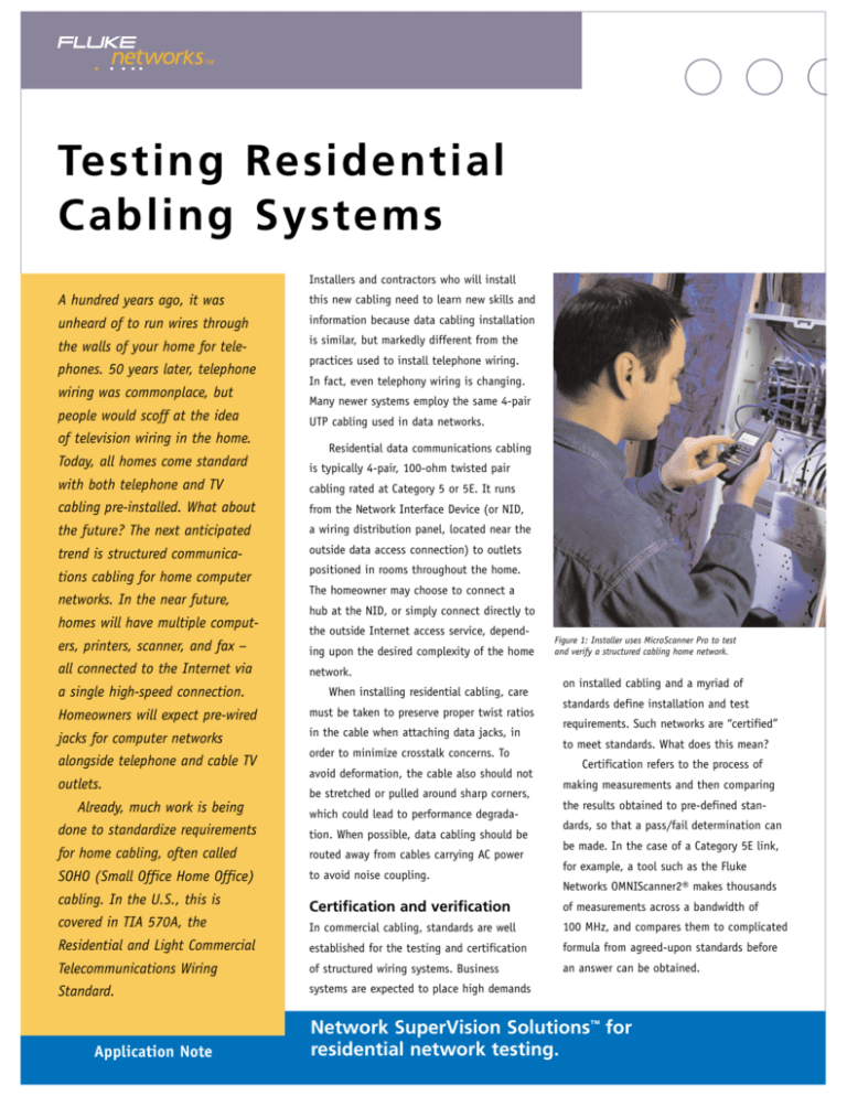
Figure 1: Installer uses MicroScanner Pro to test
and verify a structured cabling home network.
on installed cabling and a myriad of
standards define installation and test
requirements. Such networks are “certified”
to meet standards. What does this mean?
Certification refers to the process of
making measurements and then comparing
the results obtained to pre-defined standards, so that a pass/fail determination can
be made. In the case of a Category 5E link,
for example, a tool such as the Fluke
Networks OMNIScanner2® makes thousands
Certification and verification
of measurements across a bandwidth of
covered in TIA 570A, the
In commercial cabling, standards are well
100 MHz, and compares them to complicated
Residential and Light Commercial
established for the testing and certification
formula from agreed-upon standards before
Telecommunications Wiring
of structured wiring systems. Business
an answer can be obtained.
Standard.
systems are expected to place high demands
Application Note
Network SuperVision Solutions™ for
residential network testing.
In contrast, most home wiring systems
wiring and common errors are shown in
are “verified.” Verification ensures that basic
Figure 2, while a typical fault displayed in
continuity and correct terminations have
a field tester is shown in Figure 3.
been applied, but does not attempt to measure the information-carrying capacity of the
link. This is a reasonable simplification to
Figure 3: Wiring Fault and Field Tester Wiremap Display
make, because home networking links are
allows you to see how far away an open or
considerably shorter than commercial wiring
shorted event is. In the preceding example,
links.
a TDR function (usually called length meas-
Because the links are shorter, they do
not suffer nearly as much from attenuation
losses. Since the signal is typically much
stronger, impairments such as near end
crosstalk (NEXT), far end crosstalk (FEXT),
or return loss are much less of a concern.
urement) might tell you pin 2 is open at
Diagnostics
What happens when a fault is detected?
First, you want to correctly identify it in
order to fix the problem quickly. This means
diagnostic functions in your tester are use-
Wiremap
ful. For example, let’s say your wiremap
In verifying residential wiring, the most
tester tells you pin 2 is open or missing.
important measurement or diagnostic is
Where is it open? At the local connection?
wiremap. Wiremap ensures proper pin-to-pin
10 feet away? 30 feet away? 50 feet away?
connectivity between both ends of the link
At the far end connector? You could waste a
(see Figure 2). In the home, a cable could
lot of time trying to find the source of the
be cut or shorted by a nail or staple. It
problem with visual inspection. And what if
could be incorrectly terminated or miswired.
much of the cable is hidden in the wall? This
It could be damaged by other construction
is why TDR (Time Domain Reflectometry)
processes. A good wiremap tester will quickly
functions are extremely handy in a field
find any breaks, shorts, or miswires. Correct
tester. TDR is like “cable radar,” and it
33 feet; whereas the cable itself is 58 feet
long.
And what is at the far end of the cable?
It is open? Shorted? Connected to a hub?
The ability of the tester to identify what is
happening at the far end also saves time
when troubleshooting. Figure 4 indicates a
field tester screen identifying the length of
the cable and the nature of the far end termination. The connection is to an inactive
network hub. If the hub was active, the
speed (10/100) of the connection would be
indicated.
Figure 4: Field Tester Identifying Length and
Termination of an Unknown Cable
UTP and Coax
In residential applications, it is useful to
have this length function be supported for
both twisted pair and coaxial copper cable.
Then you can troubleshoot telephone, data,
and CATV cabling problems with a single
tester. Length is also useful because it
allows you to measure and record the total
length of installed cabling for documentaFigure 2: Common Wiring Errors
tion and billing purposes.
Another popular troubleshooting tool is
the toner/probe. This is actually a pair of
tools used together. The toner generates a
special signal on an attached cable. The
probe “listens” for the signal, and when its
tip is in close proximity to the cable, sounds
an audible musical tone. The closer the tip
is to the cable, the louder the sound. This is
useful when you need to identify one cable
from a group clustered together, or find a
cable that might be hidden behind a wall.
You attach the toner to the known end and
set it to generate the signal. Then you
sweep the probe across all the potential
far ends or cabled areas, and listen for the
distinctive tone.
Home networks are being installed at an
ever increasing rate. Within five to ten years,
they will be commonplace. They represent a
great opportunity for residential cabling
installers to provide a useful service with
good profit margins. However, data cabling
requires a bit more than the “install and
forget” methodology. Simple tests to verify
your residential cabling is installed correctly
and professionally will lead to increased
customer satisfaction and repeat business.
N E T W O R K S U P E R V I S I O N
Fluke Networks, Inc.
P.O. Box 9090, Everett, WA USA 98206
Fluke Europe B.V.
P.O. Box 1186, 5602 BD
Eindhoven, The Netherlands
For more information call:
U.S.A. (800) 283-5853 or
Fax (425) 446-5043
Europe/M-East/Africa (31 40) 2 675 200 or
Fax (31 40) 2 675 222
Canada (800) 363-5853 or
Fax (905) 890-6866
Other countries (425) 446-4519 or
Fax (425) 446-5043
E-mail: fluke-assist@flukenetworks.com
Web access: http://www.flukenetworks.com
©2002 Fluke Networks, Inc. All rights reserved.
1/2002 1665715 A-ENG-N Rev A

