Recovering Air Handler Condensate - International District Energy
advertisement
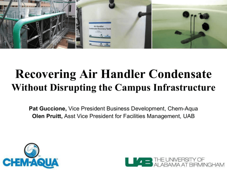
Recovering Air Handler Condensate Without Disrupting the Campus Infrastructure Pat Guccione, Vice President Business Development, Chem-Aqua Olen Pruitt, Asst Vice President for Facilities Management, UAB The University of Alabama at Birmingham The University of Alabama at Birmingham • UAB is a research university and academic health center • 18,619 employees (Alabama’s largest employer) • $4.6 billion annual economic impact • 17,543 students • 166 owned buildings and 50 leased buildings • 16 million square feet of space Three Central Plants Physical Plant Operations • 15 centrifugal chillers (2,000 to 4,000 tons) • 19 cooling towers • Nine condenser systems • 42°F supply • 54°F return • PLC controlled to maximize operation and efficiency UAB Physical Plant • 52 of our most critical buildings served – Approximately 8 million ft2 • 60% of the buildings are hospital operations • 40% are research labs and comfort cooling • Every building is connected to the distribution system with a flow meter measuring CHW flow – Supply and return temperatures are also recorded – Buildings are charged monthly for MMBTU usage Central Plant #3 FUTURE UAB Building with Fin Water Recovery System Central Plant #1 Central Plant #5 UAB Physical Plant • 2006 chilled water production – 81 million ton-hours • 2010 chilled water production – Over 99 million ton-hours – 18% increase • 2010 power consumption – 93 million kwh – This is 33% of total energy consumed by UAB Other Physical Plant Projects • Removed all three-way valves in entire distribution system – Eliminated low delta T syndrome – Increased delta T, which increased overall efficiency • High-efficiency cooling towers – Replaced old 78°F wet bulb towers with new high-efficiency 80°F wet bulb towers – Allowed us to reduce entering condenser water temperatures below design • Average chiller efficiency is now 0.59 kw/ton UAB Background • Reliability of water supply is mission critical at UAB • Hospital Critical Care Units – A/C is a life-support issue – Temperature dependent surgeries • Specialized Research Labs – Animal housing and procedural space – Research stored in freezers sensitive to temperature UAB Challenges Regarding Water Supply • Frequent droughts in the Southeast US • Typically are water restrictions every year • Squabbles over intra-state water rights • 86 blocks of campus • Alabama experiences about 100 days of very hot summer weather UAB Central Chilled Water System During peak hot summer months, over 1.2 million gallons of makeup water required per day for the cooling towers due to evaporative and blowdown losses. UAB Challenges Regarding Water Supply The Solution Recover and use the millions of gallons of high-quality condensate water currently going down the drain. UAB Challenges Regarding Water Supply The Obstacle Most of the condensate would be collected blocks and blocks from the towers. It would be cost prohibitive and very disruptive to dig up the streets in downtown Birmingham for this project. UAB Challenges Regarding Water Supply Potential Solution for this Obstacle Rather than installing a dedicated distribution system to pipe the air handler condensate back to the chilled water plant’s cooling tower, use the existing chilled water distribution system piping as a transport system to get the condensate from the buildings to the main plants. Typical Collection System Building B Building A AH 1 AH 2 AH 3 110 volt Submersible Sump Pump w/ Internal Float Controller AH 4 Condensate Recovery Tank (100 gallons each) Large Collection Tank (500 gallons) Float Level Controller Data Collection F I L T E R 80 psig 45678 3 Phase 480v 55 gpm Rated Grundfos Pump C H I L L E D Chilled Water Return Line to Central Plants 65-75 psig Condensate Recovery Systems Fin Water Recovery Tank Sump Pump Discharge Fail Safe Overflow Gravity Drain Condensate Condensate Entire Fin Water Recovery System Central Plant’s Control System – relieving fin water to cooling tower Basic Concept – utilizing CHW distribution piping to transport recovered fin water to plants’ cooling towers • Over pressurize the chilled water – Typically maintain chilled water at 76 psig – Allow pressure to build by pumping in the AHC – Bleed into the towers when you exceed 76 psig • Have remote safety to cut off pressure by stopping all condensate pumps – set point 80 psig • Also, controls are programmed so if any makeup pump is running, the fin water control valve that relieves to the cooling towers remains closed Project Concerns • Success depends on the details • Uncertainty about over pressurization • Concerns about flooding in collection areas • What changes are needed in the water chemistry? • What are the increased maintenance items? Safeties and Redundancies • High pressure safety set point in PLC logic – Stops the remote collection pumps in case the pressure builds above 80 psig • All collection tanks and pumping tanks fail back to drain by gravity – To protect against power outage or pump failure • The discharge temperature of the water at each pumping location is monitored with RTD’s – Indicates that water is actually being pumped – If the temperature increases, the water is not flowing Water Chemistry • Now we are putting “pure” distilled quality water into the chilled water loop • Plus, this water is “oxygen rich” – Required a change in corrosion inhibition • AHC water is “dirty” – Required filtration plus a biological control package • Chilled water chemistry must be compatible with cooling tower water chemistry • Cooling tower program must be adjusted to allow for variable makeup water quality Condensate Recovery Systems Filtration is Necessary Planned Changes to Water Chemistry • Change conventional chilled water program to silica/azole-based inhibition package • Use chlorine dioxide (ClO2) as biological control program for chilled water • Tower treatment program was profiled to ensure compatibility with chemistry being added to the chilled water Additional Program Benefits • Allowed us to eliminate bromine from cooling tower treatment program – Availability of ClO2 generators allowed for the low-cost addition of ClO2 to the towers – Feed the ClO2 based on makeup water • ATP and dip slide results in towers are excellent ClO2 Generators • Three Pureline PureClO2 model HP-10 – 10 pounds per day (ppd) of ClO2 each – One installed at each of the three central plants – Can feed both the chilled water and the condenser water – Monitored by SensoreX low-range ClO2 probes ClO2 Residuals Chilled Water MB Results Corrosion Rates via Corrator Average Copper Corrosion Rate: 0.025 mpy Average Mild Steel Corrosion Rate: 0.015 mpy Project ROI ROI Calculated on a “Per Building” Basis Example Bevill Biomedical Research Building • 223,712 gsf • 100% outside air • Condensate collected from five air handlers • Peak gpm = 5 • Annual gallons 1.29 million/year • Water cost = $3.12/ccf • Annual savings $27,027.00 • Estimated project costs $32,914.00 • Simple payback is approximately 1.2 years ROI was calculated on water savings ONLY UAB: The Challenges • Focus on ROI first – Many research and healthcare buildings are turning the air 25-40 turns per hour – Typically need a 15-18 month payback to justify • Sell the building occupants • Convince veteran maintenance and operating staff – Get their ideas and input Program Results • First recovery system installed May 2011 at McCallum – Kaul buildings. The other systems were phased in during the year. • Since May 2011 we have collected 3.7 million gallons. • Currently we have six large research buildings with fin water recovery systems in place. With these six buildings we project to collect over 10 million gallons in 2012. • Before summer 2012, two more large research buildings will be online. Conclusions Benefits • Reducing wastewater • Reducing domestic water usage • By making up CHW losses with 45° water instead of 70° water, saved 730 MM BTU – Approx $10,000/year • Using the cold condensate provides additional free cooling of the cooling tower circulating water – Approx. 1° better than design on approach Goals • Get to 15,000,000 gallons recovered in 2012 • Get to 20,000,000/year recovered within three to five years • As new buildings are constructed, build the fin water recovery system into the plan during the design phase
