Document
advertisement

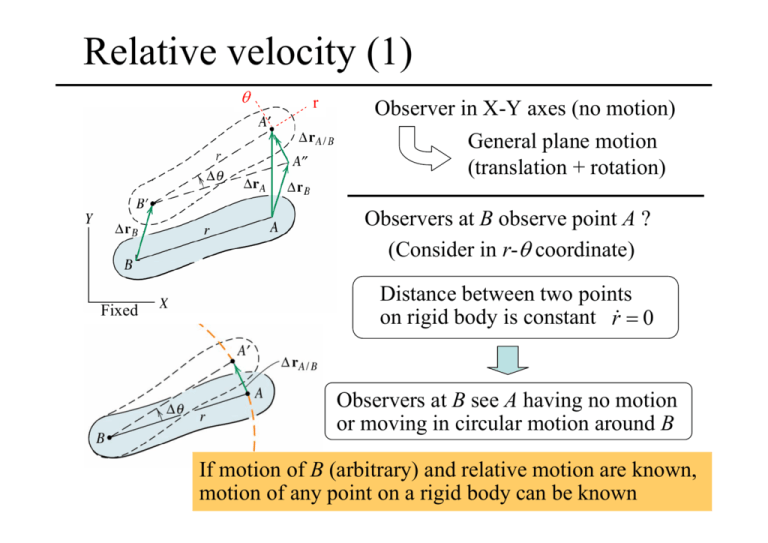
Relative velocity (1) θ r Observer in X-Y axes (no motion) General plane motion (translation + rotation) Observers at B observe point A ? (Consider in r-θ coordinate) Fixed Distance between two points on rigid body is constant r& = 0 Observers at B see A having no motion or moving in circular motion around B If motion of B (arbitrary) and relative motion are known, motion of any point on a rigid body can be known Relative velocity (2) Consider the movement from 1 to 2 shown by line BA 2 1 Step 1: translation BA ⇒ B′A′′ v ΔrB = Displacement vector (translation) Step 2: rotation about point B' B′A′′ ⇒ B′A′ v ΔrA / B = change in position of A in this step = change in position of A (observed by observer at B) Δθ = change in the angle of line BA Total change in position of A v v v ΔrA = ΔrB + ΔrA / B Relative velocity (3) v v v ΔrA = ΔrB + ΔrA / B Divide by Δt and take limit Δt → 0 v v v v A = vB + v A / B v Similarly, from ΔrA/ B = rΔθ v A / B = rω In vector form v v v vA/ B = ω × r Observers at B see point A moving in a circle around point B with the angular velocity of the body ω Relative velocity (4) Observers at B see point A moving in a circle around point B v v A / B is always perpendicular to the line AB Solving the problems Concept: • Observer at B see point A moving in a circle around B • Point A moving in circular motion Magnitude v A / B 1. Write eq.; Check known, unknown quantities v v v v A = vB + v A / B Mag. Dir. × × rω ⊥ AB Which case? Mag. Dir. × × ⊥ AB = rω, Direction ⊥ AB 2. Calculate known quantities, angles 3. Draw vector diagram v vB v vA/ B (⊥ AB ) v vA 4. Calculate required quantities Ex. Using sine law, cosine law Sample problem 5/7 The wheel of radius r = 300 mm rolls to the right without slipping and has a velocity vO = 3 m/s of its center O. Calculate the velocity of point A on the wheel for the instant represented. Sample problem 5/8 Crank CB oscillates about C through a limited arc, causing crank OA to oscillate about O. When the linkage passes the position shown with CB horizontal and OB vertical, the angular velocity of CB is 2 rad/s counterclockwise. For this instant, determine the angular velocities of OA and AB. Sample problem 5/9 The common configuration of a reciprocating engine is that of the slider crank mechanism shown. If the crank OB has a clockwise rotational speed of 1500 rev/min, determine for the position where θ = 60° the velocity of the piston A, the velocity of point G on the connecting rod, and the angular velocity of the connecting rod. Sample problem 5/10 The power screw turns at a speed which gives the threaded collar C a velocity of 0.25 m/s vertically down. Determine the angular velocity of the slotted arm when θ = 30°. Sample 5 (5/77) The flywheel turns clockwise with a constant speed of 600 rev/min, and the connecting rod AB slides through the pivoted collar at C. For the position θ = 45°, determine the angular velocity ωAB of AB by using the relative-velocity relations. (Suggestion: Choose a point D on AB coincident with C as a reference point whose direction of velocity is known.) Sample 6 (5/87) Pin P on the end of the horizontal rod slides freely in the slotted gear. The gear engages the moving rack A and the fixed rack B (teeth not shown) so it rolls without slipping. If A has a velocity of 120 mm/s to the left for the instant shown, determine the velocity vP of the rod for this position. Sample 7 (5/89) The wheel rolls without slipping. For the instant portrayed, when O is directly under point C, link OA has a velocity v = 1.5 m/s to the right and θ = 30°. Determine the angular velocity ω of the slotted link. Instantaneous Center of Zero Velocity Rigid body : distances between any two points are constant Consider ω of each line, if ω of lines are different B A C D • Line AB and CD rotate at different ω • Distances between two lines (points) are changed Impossible • All lines in the rigid body must rotate with the same ω • There is a point that is the center of rotation of all points in the rigid body at that instant • If this point is known, v at any point can be calculated v=0 v = ωr Instantaneous Center of Zero Velocity • For a moving body at each instant of time, there is always a point on the body (or on the extended body) that can be though as the center of rotation. • This point has zero velocity ,and be called as “Instantaneous center of zero velocity (I.C.Z.V)” v v 0 v v A = vC + v A / C Absolute velocity = relative velocity (Observing from an I.C.Z.V) v v v vA = ω × r (I.C.Z.V) Observer v v A must be perpendicular to CA Locating the instantaneous center v v A perpendicular to CA v vB perpendicular to CB vA = ω(CA) vB = ω(CB) Although vC = 0, aC usually ≠ 0 (see sample) Point C (I.C.Z.V) can be used for calculating velocity only. Motion of the instantaneous center As the body changes its position, the instantaneous center also changes it position. Consider in body: I.C.Z.V move along this locus Body centrode t1 I.C.Z.V t2 I.C.Z.V Consider in space: I.C.Z.V move along this locus Space centrode Example I.C.Z.V Space centrode C A Body centrode vA B vB The change of the position of I.C.Z.V in the space A B The change of the position of I.C.Z.V relative to bar AB Sample problem 5/11 The wheel rolls to the right without slipping, with its center O having a velocity vO = 3 m/s. Locate the instantaneous center of zero velocity and use it to find the velocity of point A for the position indicated. Sample problem 5/12 Arm OB of the linkage has a clockwise angular velocity of 10 rad/s in the position shown where θ = 45°. Determine the velocity of A, the velocity of D, and the angular velocity of link AB for the position shown. Sample 8 (5/113) Vertical oscillation of the spring-loaded plunger F is controlled by a periodic change in pressure in the vertical hydraulic cylinder E. For the position θ = 60°, determine the angular velocity of AD and the velocity of the roller A in its horizontal guide if the plunger F has a downward velocity of 2 m/s. Sample 9 (5/115) The three gears 1, 2, and 3 of equal radii are mounted on the rotating arm as shown. (Gear teeth are omitted from the drawing.) Arm OA rotates clockwise about O at the angular rate of 4 rad/s, while gear 1 rotates independently at the counterclockwise rate of 8 rad/s. Determine the angular velocity of gear 3. Sample 10 (5/117) The shaft at O drives the arm OA at a clockwise speed of 90 rev/min about the fixed bearing O. Use the method of the instantaneous center of zero velocity to determine the rotational speed of gear B (gear teeth not shown) if (a) ring gear D is fixed and (b) ring gear D rotates counterclockwise about O with a speed of 80 rev/min.


