WAVE SHAPING CIRCUITS DIODE LIMITERS POSITIVE LIMITER
advertisement
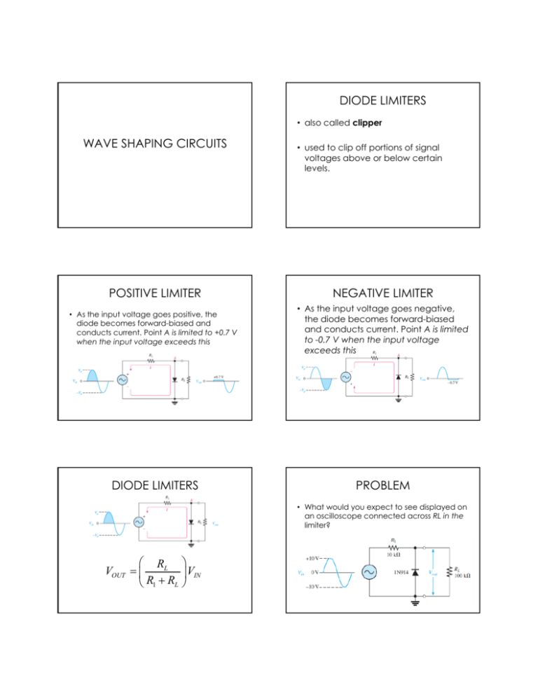
DIODE LIMITERS • also called clipper WAVE SHAPING CIRCUITS • used to clip off portions of signal voltages lt above b or below b l certain t i levels. POSITIVE LIMITER NEGATIVE LIMITER • As the input voltage goes positive, the diode becomes forward-biased and conducts current. Point A is limited to +0.7 V when the input voltage exceeds this • As the input voltage goes negative, the diode becomes forward-biased and conducts current. Point A is limited to -0.7 V when the input voltage exceeds d thi this DIODE LIMITERS PROBLEM • What would you expect to see displayed on an oscilloscope connected across RL in the limiter? RL VOUT VIN R R L 1 BIASED LIMITERS • The level to which an ac voltage is limited can be adjusted by adding a bias voltage, Vbias , in series with the diode NEGATIVE BIASED LIMITERS • The voltage at point A must equal -Vbias - 0.7 V before the diode will become forward-biased and conduct. • Once the diode begins to conduct, the voltage at point A is limited to -V Vbias - 0.7 0 7 V so that all input bi voltage above this level is clipped off. DIODE CLAMPERS • used to add or restore a dc level to an electrical signal • sometimes ti k known as dc d restorers. t POSITIVE BIASED LIMITERS • The voltage at point A must equal Vbias + 0.7 V before the diode will become forward-biased and conduct. • Once the diode begins to conduct, the voltage at point A is limited to Vbias + 0.7 0 7 V so that all input bi voltage above this level is clipped off. PROBLEM • Determine the output wave form POSITIVE CLAMPER • a diode clamper that inserts a positive dc level in the output waveform. • The operation of this circuit can be seen by considering the first negative half-cycle of the input voltage. When the input voltage initially goes negative, negative the diode is forward-biased, forward biased allowing the capacitor to charge to near the peak of the input NEGATIVE CLAMPER


