Voltage Doubler Basics
Online lecture slides for lesson 1418-1 Cleveland Institute of Electronics
Components, use and operation
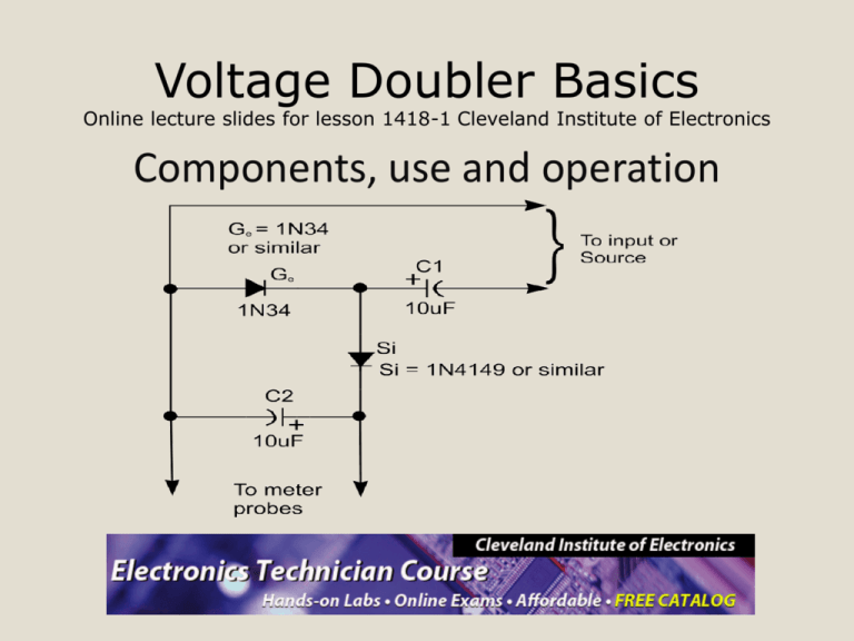
Components of Voltage Doubler
• There are basically two types of
components to a Voltage Doubler.
– Two 10μF capacitors
– One Silicon Diode
– One Germanium Diode
Diodes
• Diodes are semiconductors
– Any of the various solid crystalline
substances, such as germanium or silicon,
having electrical conductivity greater than
insulators.
Schematic Symbol of a Diode
Cathode
Anode
Pictorial View of a Diode
Cathode
Anode
Parts of a diode
Cathode
Anode
The anode is more positive
than the Cathode.
Basic diode operation
• A diode acts as a one-way valve to
electricity/current flow.
– This means current will only flow in one
direction
– Current flows from negative to positive, so
from cathode to anode. (Forward Biased) (On
Switch)
– If the diode is Reversed Biased, current does
not flow (Off/Open Switch)
• Diodes are made of silicon or germanium
• Silicon diodes drop approximately
0.5 - 0.7 Volts when forward biased.
• Germanium diodes drop approximately
0.3 – 0.4 Volts when forward biased
– The diodes are conducting when forward
biased
– Forward Biased: The voltage at the Anode
is more positive than Cathode voltage
Electrolytic Capacitors
• Take care to place the capacitor correctly
in the circuit. Electrolytic capacitors have
a polarity marked on the capacitor’s case
• Take care not to exceed the voltage
marked on the capacitor’s case
• Note the negative lead is shorter than
the positive lead, or the positive lead is
longer
• Other types of capacitors do not have a
polarity and have different functions in
circuits
Pictorial View of an Electrolytic Cap
Positive
Schematic Symbol of an
Electrolytic Capacitor
Voltage Doubler in 1418-1
Things to Remember about
Voltage Doublers
• We are using the Voltage Doubler
primarily with the Analog Multimeter to
measure extremely small values.
• The Silicon (Si) and the Germanium (Ge)
diodes can swap positions in the circuit
and the circuit will work fine.
• Remember: The Blocking Capacitor
coming from the sine wave generator on
the trainer is used only with Analog
Multimeters.
• Digital Multimeters do not need the
Blocking Capacitor
– You will not measure a signal if the
blocking capacitor is used
• There is already one built into the meter
• Make sure the polarity of the diodes and
electrolytic capacitors are correct before
applying power.
• It does not matter if you ground pin 1 or
pin 2 of the potentiometer.
• You can use pin 1 or pin 3 with pin 2 as
long as either pin 1 or 3 are not
connected/open.
Voltage Doubler in 1418-1
Voltage Doubler Operation
• C2 charges, to 5 V (4.5 V considering
the diode drop) on the negative half cycle
of AC input. The right end is grounded by
the conducting diode Ge. The left end is
charged at the negative peak of the AC
input. This is the operation of the clamper.
• During the positive half cycle, the halfwave rectifier comes into play. Diode Ge is
out of the circuit since it is reverse biased.
C2 is now in series with the voltage source.
Note the polarities of the generator and C2,
series aiding.
Thus, rectifier diode Si sees a total of 10 V
at the peak of the sinewave, 5 V from
generator and 5 V from C2. Si conducts,
charging C1 to the peak of the sine wave
riding on 5 V DC. The output of the
doubler, stabilizes at 10 V (8.9 V with
diode drops) after a few cycles of sinewave
input.
Voltage Doubler Breadboarded
Circuit with Voltage Doubler
Questions?
The End
Developed and Produced by the
Instructors in the CIE Instruction
Department.
© Copyright 11/2011
All Rights Reserved / Nov. 2011


