1762-DU001B-EN-P, MicroLogix 1200 and MicroLogix 1500
advertisement
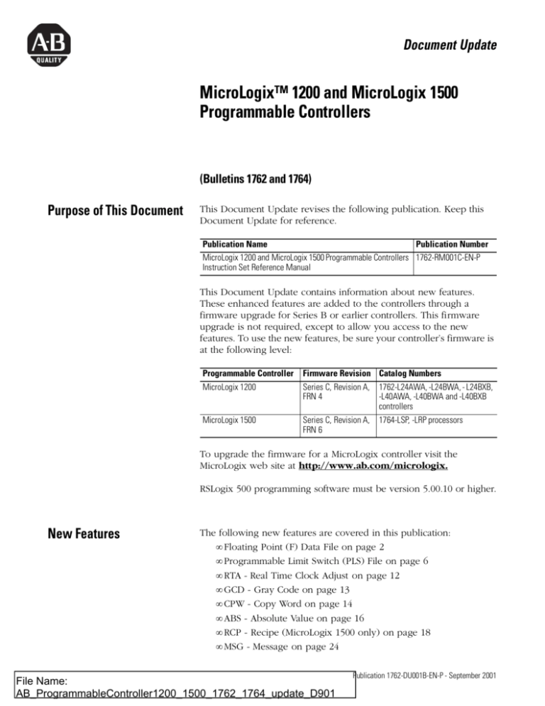
Document Update MicroLogix™ 1200 and MicroLogix 1500 Programmable Controllers (Bulletins 1762 and 1764) Purpose of This Document This Document Update revises the following publication. Keep this Document Update for reference. Publication Name Publication Number MicroLogix 1200 and MicroLogix 1500 Programmable Controllers 1762-RM001C-EN-P Instruction Set Reference Manual This Document Update contains information about new features. These enhanced features are added to the controllers through a firmware upgrade for Series B or earlier controllers. This firmware upgrade is not required, except to allow you access to the new features. To use the new features, be sure your controller’s firmware is at the following level: Programmable Controller MicroLogix 1200 MicroLogix 1500 Firmware Revision Catalog Numbers Series C, Revision A, 1762-L24AWA, -L24BWA, - L24BXB, FRN 4 -L40AWA, -L40BWA and -L40BXB controllers Series C, Revision A, 1764-LSP, -LRP processors FRN 6 To upgrade the firmware for a MicroLogix controller visit the MicroLogix web site at http://www.ab.com/micrologix. RSLogix 500 programming software must be version 5.00.10 or higher. New Features 1 The following new features are covered in this publication: • Floating Point (F) Data File on page 2 • Programmable Limit Switch (PLS) File on page 6 • RTA - Real Time Clock Adjust on page 12 • GCD - Gray Code on page 13 • CPW - Copy Word on page 14 • ABS - Absolute Value on page 16 • RCP - Recipe (MicroLogix 1500 only) on page 18 • MSG - Message on page 24 File Name: AB_ProgrammableController1200_1500_1762_1764_update_D901 Publication 1762-DU001B-EN-P - September 2001 2 MicroLogix™ 1200 and MicroLogix 1500 Programmable Controllers Floating Point (F) Data File File Description Floating point files contain IEEE-754 floating point data elements. One floating point element is shown below. You can have up to 256 of these elements in each floating point file. Floating Point Data File Structure Floating Point Element 31 30 29 28 27 26 25 24 23 22 21 20 19 18 17 16 15 14 13 12 11 10 09 08 07 06 05 04 03 02 01 00 Mantissa S(1) Exponent Value High Word Low Word (1) S = Sign Bit Floating point numbers are represented using the IEEE-754 format, where: • Bit 31 is the sign bit. This bit is set for negative numbers (note that negative zero is a valid value). • Bits 23 to 30 are the exponent. • Bits 0 to 22 are the mantissa. The value represented by a 32-bit floating point number (not one of the exception values defined on page 3) is given by the following expression. Note the restoration of the suppressed most significant bit of the mantissa. (-1)s x 2 e - 127 x (1 + m) where: s is the sign bit (0 or 1) e is the exponent (1 to 254) m is the mantissa (0 ≤ f < 1) The valid range for floating point numbers is from -3.4028 x 1038 to +3.4028 x 1038. Definitions Overflow - occurs when the result of an operation produces an exponent that is greater than 254. Underflow - occurs when the result of an operation produces an exponent that is less than one. Publication 1762-DU001B-EN-P - September 2001 MicroLogix™ 1200 and MicroLogix 1500 Programmable Controllers 3 Floating Point Exception Values Zero - represented by an exponent and a mantissa of zero. Both positive and negative zero are valid. Denormalized - represented by an exponent of zero and a non-zero mantissa part. Since denormalized numbers have very small, insignificant values, they are treated as zero when used as source operand for most instructions. This reduces execution time. Denormalized numbers are not generated by the instructions (but are propagated by some instructions). Zero is generated on an underflow. Infinity - represented by an exponent of 255 and a mantissa part of zero. Both positive and negative infinity are generated when operations overflow. Infinity is propagated through calculations. NAN (not a number) - is represented by an exponent of 255 and a non-zero mantissa part. NANs are used to indicate results that are mathematically undefined such as 0/0 and adding plus infinity to minus infinity. All operations given a NAN as input must generate a NAN as output. LSB Round-to-Even Rule Floating point operations are rounded using the round-to-even rule. If the bits of the result to the right of the least significant bit (LSB) represent a value less than one-half of the LSB, then the result remains as is. If the bits to the right of the LSB represent a value greater than one-half of the LSB, the result is rounded up by adding one LSB. If the bits to the right of the LSB represent a value of exactly one-half LSB, the result is rounded up so that the LSB is an even number. Addressing Floating Point Files The addressing format for floating point data files is shown below. Format Ff:e Examples: Explanation F Floating Point file f File number : Element delimiter e Element number F8:2 F10:36 The valid file number range is from 8 (default) to 255. The valid element number range is from 0 to 255. Floating Point File 8, Element 2 Floating Point File 10, Element 36 Publication 1762-DU001B-EN-P - September 2001 4 MicroLogix™ 1200 and MicroLogix 1500 Programmable Controllers Data File Download Protection Download File Protection can be applied to Floating Point Data Files. See page 2-6 of the Instruction Set Reference Manual for more information on protecting data files during download. Programming Floating Point Values The following table shows which instructions can use floating point data. The information in the table is in addition to the current information shown in the Instruction Set Reference Manual. Mnemonic Description Manual Considerations When Using Floating Point Data Page Compare Instructions 9-2 Equal EQU Greater Than or Equal To GEQ Greater Than GRT Less Than or Equal To LEQ Less Than LES Limit Test LIM Not Equal NEQ Math Instructions ABS Absolute Value Add ADD Clear CLR Divide DIV Multiply MUL Negate NEG Square Root SQR Subtract SUB When at least one of the operands is a Floating Data Point value: • For EQU, GEQ, GRT, LEQ, and LES - If either Source is NAN, then rung state changes to false. • For NEQ - If either Source is NAN, then rung state remains true. n/a New Instruction - see page 16 of this Document Update. 10-2 and When at least one of the operands is a Floating Data Point value: 10-3 • If either Source is NAN, then the result is NAN. • All overflows result in infinity with the correct sign. • All underflows result in plus zero. • All denormalized Source values are treated as plus zero. • Results are always rounded using the Round to Even rule. • If Destination is an integer and the result is NAN or infinity, a saturated result (-32768 or +32767 for word or -2,147,836,648 or +2,147,836,647 for long word) is stored in Destination and the Math Overflow Selection Bit is ignored. • If Destination is an integer, the rounded result is stored. If an overflow occurs after rounding, a saturated result is stored in Destination and the Math Overflow Selection Bit is ignored. The saturated results are: – If Destination is an integer and the result is positive, overflow Destination is +32767 (word) or +2,147,483, 648 (long word). – If Destination is an integer and the result is negative, overflow Destination is -32767 (word) or -2,147,483, 648 (long word). Updates to Math Status Bits: • Carry - is reset • Overflow - Is set if the result is infinity, NAN, or if a conversion to integer overflows; otherwise it is reset. • Zero - Is set if the lower 31 bits of the Floating Point Data result is all zero’s, otherwise it is reset. • Sign - Is set if the most significant bit of the Destination is set (bit 15 for word, bit 31 for long word or floating point data); otherwise it is reset. • Overflow Trap - The Math Overflow Trap Bit is only set if the Overflow bit is set. Otherwise, it remains in its last state. Publication 1762-DU001B-EN-P - September 2001 MicroLogix™ 1200 and MicroLogix 1500 Programmable Controllers Mnemonic Description 5 Manual Considerations When Using Floating Point Data Page Move Instructions MOV Move 13-1 When at least one of the operands is a Floating Data Point value: • The result is an exact copy of Source (preserving infinity, NAN, and denormalized values). • If Destination is an integer and Source is NAN or infinity, a saturated result (32767 for word or 2,147,836,647 for long word) is stored in Destination and the Math Overflow Selection Bit is ignored. • If Destination is an integer, the rounded result is stored. If an overflow occurs after rounding, a saturated result (32767 for word or 2,147,836,647 for long word) is stored in Destination and the Math Overflow Selection Bit is ignored. Updates to Math Status Bits: • Carry - is reset • Overflow - Is set if the result is infinity, NAN, or if a conversion to integer overflows; otherwise it is reset. • Zero - Is set if Destination is all zero’s, otherwise it is reset. • Sign - Is set if the most significant bit of the Destination is set (bit 15 for word, bit 31 for long word or floating point data); otherwise it is reset. • Overflow Trap - The Math Overflow Trap Bit is only set if the Overflow bit is set. Otherwise, it remains in its last state. File Instructions CPW Copy Word FLL Fill File n/a 14-3 New Instruction - see page 14 of this Document Update. For Floating Point Data: • Source can be any IEEE-754 32-bit value. • Length can range from 1 to 64. Communication Instructions MSG Message 21-13 When using Floating Point Data: • Data Table Address/Offset - The Local File Type and Target File Type must both be Floating Point. NOTE: There are no special rules for sending or receiving floating point data. It is treated like any other data file type. • The Message Type must be 500CPU or PLC5. NOTE: The MicroLogix 1200 or MicroLogix 1500 can send or receive floating point data to or from SLC 500 and PLC-5 processors. Publication 1762-DU001B-EN-P - September 2001 6 MicroLogix™ 1200 and MicroLogix 1500 Programmable Controllers Programmable Limit Switch (PLS) File The Programmable Limit Switch function allows you to configure the High-Speed Counter to operate as a PLS (programmable limit switch) or rotary cam switch. When PLS operation is enabled, the HSC (High-Speed Counter) uses a PLS data file for limit/cam positions. Each limit/cam position has corresponding data parameters that are used to set or clear physical outputs on the controller’s base unit. The PLS data file is illustrated below. IMPORTANT The PLS Function only operates in tandem with the HSC of a MicroLogix 1200 or 1500. To use the PLS function, an HSC must first be configured. PLS Data File Data files 9 to 255 can be used for PLS operations. Each PLS data file can be up to 256 elements long. Each element within a PLS file consumes 6 user words of memory. The PLS data file is shown below: PLS Operation When the PLS function is enabled, and the controller is in the run mode, the HSC will count incoming pulses. When the count reaches the first preset (High - HIP or Low - LOP) defined in the PLS file, the output source data (High - OHD or Low - OLD) will be written through the HSC mask. At that point, the next preset (High - HIP or Low - LOP) defined in the PLS file becomes active. When the HSC counts to that new preset, the new output data is written through the HSC mask. This process continues until the last Publication 1762-DU001B-EN-P - September 2001 MicroLogix™ 1200 and MicroLogix 1500 Programmable Controllers 7 element within the PLS file is loaded. At that point the active element within the PLS file is reset to zero. This behavior is referred to as circular operation. TIP The Output High Data (OHD) is only written when the High preset (HIP) is reached. The Output Low Data (OLD) is written when the low preset is reached. TIP Output High Data is only operational when the counter is counting up. Output Low Data is only operational when the counter is counting down. If invalid data is loaded during operation, an HSC error is generated (within the HSC function file). The error will not cause a controller fault. If an invalid parameter is detected, it will be skipped and the next parameter will be loaded for execution (provided it is valid). You can use the PLS in Up (high), Down (low), or both directions. If your application only counts in one direction, simply ignore the other parameters. The PLS function can operate with all of the other HSC capabilities. The ability to select which HSC events generate a user interrupt are not limited. Addressing PLS Files The addressing format for the PLS file is shown below. Format PLSf:e.s Explanation PLS Programmable Limit Switch file f File number The valid file number range is from 9 to 255. : Element delimiter e Element number The valid element number range is from 0 to 255. . Sub-Element delimiter s Sub-Element number The valid sub-element number range is from 0 to 5 Examples: PLS10:2 PLS File 10, Element 2 PLS12:36.5 PLS File 12, Element 36, Sub-Element 5 (Output Low Source) Publication 1762-DU001B-EN-P - September 2001 8 MicroLogix™ 1200 and MicroLogix 1500 Programmable Controllers PLS Example Setting up the PLS File 1. Using RSLogix 500, create a new project, give it a name and select the appropriate controller. 2. Right click on Data Files and select New. Publication 1762-DU001B-EN-P - September 2001 MicroLogix™ 1200 and MicroLogix 1500 Programmable Controllers 9 3. Enter a file number (9 to 255) and select Programmable Limit Switch as the type. A Name and/or Description may be entered as well, but is not required. 4. Elements refers to the number of PLS steps. For this example enter a value of 4. If more steps are required at a later time, simply go to the properties for the PLS data file and increase the number of elements. 5. Under Data Files, PLS10 should appear as shown to the left. Publication 1762-DU001B-EN-P - September 2001 10 MicroLogix™ 1200 and MicroLogix 1500 Programmable Controllers 6. Double-click on PLS10 under Data Files. For this example, enter the values as illustrated below. PLS Data File Definitions: Data HIP LOP OHD OLD Description High Preset Low Preset Output High Data Output Low Data Data Format 32-bit signed integer 16-bit binary (bit 15--> 0000 0000 0000 0000 <--bit 0) Once the values above have been entered for HIP and OHD, the PLS is configured. Configuring the HSC for Use with the PLS 1. Under Controller, double-click on Function Files. 2. For HSC:0, configure the HSC.MOD to use PLS10 and for the HSC to operate in mode 00. IMPORTANT The value for MOD must be entered in Hexadecimal. For example, PLS10 = 0A and HSC Mode = 00 Publication 1762-DU001B-EN-P - September 2001 MicroLogix™ 1200 and MicroLogix 1500 Programmable Controllers 11 PLS Operation for This Example When the ladder logic first runs, HSC.ACC equals 0, therefore PLS10:0.OLD's data is sent through the HSC.OMB mask and sets all the outputs off. When HSC.ACC equals 250, the PLS10:0.OHD is sent through the HSC.OMB mask and energizes the outputs. This will repeat as the HSC.ACC reaches 500, 750, and 1000. Once completed, the cycle resets and repeats. Publication 1762-DU001B-EN-P - September 2001 12 MicroLogix™ 1200 and MicroLogix 1500 Programmable Controllers RTA - Real Time Clock Adjust Instruction Type: output Execution Time for the RTA Instruction RTA Real Time Clock Adjust Controller MicroLogix 1200 MicroLogix 1500 When Rung Is: True False 4.7 µs 3.7 µs 556.2 µs (false-to-true transition) 4.1 µs 2.6 µs 426.8 µs (false-to-true transition) The RTA instruction is used to synchronize the controllers Real-Time Clock (RTC) with an external source. The RTA instruction will adjust the RTC to the nearest minute. The RTA instruction adjusts the RTC based on the value of the RTC Seconds as described below. IMPORTANT The RTA instruction will only change the RTC when the RTA rung is evaluated true, after it was previously false (false-to-true transition). The RTA instruction will have no effect if the rung is always true or false. RTA is set: • If RTC Seconds are less than 30, then RTC Seconds is reset to 0. • If RTC Seconds are greater than or equal to 30, then the RTC Minutes are incremented by 1 and RTC Seconds are reset to 0. The following conditions cause the RTA instruction to have no effect on the RTC data: • No RTC attached to the controller • RTC is present, but disabled • An external (via communications) message to the RTC is in progress when the RTA instruction is executed. (External communications to the RTC takes precedence over the RTA instruction.) To re-activate the RTA instruction, the RTA rung must become false, and then true. TIP Publication 1762-DU001B-EN-P - September 2001 There is only one internal storage bit allocated in the system for this instruction. Do not use more than one RTA instruction in your program. MicroLogix™ 1200 and MicroLogix 1500 Programmable Controllers GCD - Gray Code 13 Instruction Type: output Execution Time for the GCD Instructions Dest Controller I1:2.0 225< N7:1 190< When Rung Is: True 9.5 µs 8.2 µs MicroLogix 1200 MicroLogix 1500 False 0.0 µs 0.0 µs The GCD instruction converts Gray code data (Source) to an integer value (Destination). If the Gray code input is negative (high bit set), the Destination is set to 32767 and the overflow flag is set. Addressing Modes and File Types are shown in the following table: GCD Instruction Valid Addressing Modes and File Types For definitions of the terms used in this table see Using the Instruction Descriptions on page4-2. Data Files Parameter Source Function Files Address Mode Address Level O I S B T, C, R N F ST L MG, PD RTC HSC PTO, PWM STI EII BHI MMI DAT TPI CS - Comms IOS - I/O Immediate Direct Indirect Bit Word Long Word Element GCD GCD Gray Code Source • • • • • • • • Destination • • • • • • • • Updates to Math Status Bits Math Status Bits With this Bit: S:0/0 Carry S:0/1 Overflow S:0/2 Zero Bit S:0/3 Sign Bit S:5/0 Overflow Trap The Controller: always reset set if the Gray code input is negative, otherwise is reset set if the destination is zero, otherwise reset always reset set if the Overflow Bit is set, otherwise reset Publication 1762-DU001B-EN-P - September 2001 14 MicroLogix™ 1200 and MicroLogix 1500 Programmable Controllers CPW - Copy Word Instruction Type: output Execution Time for the CPW Instruction CPW CPW Copy Word Source Dest Length Controller #HSC:0.2 #N7:0 1 MicroLogix 1200 MicroLogix 1500 When Rung Is: True 18.3 µs + 0.8 µs/word 15.8 µs + 0.7 µs/word False 0.0 µs 0.0 µs The CPW instruction copies words of data, in ascending order, from one location (Source) to another (Destination). Although similar to the File Copy (COP) instruction, the CPW instruction allows different source and destination parameters. Examples include: • • • • integer to long word long word to floating point long word to integer integer to PTO function file Observe the following restrictions when using the CPW instruction: • The length of the data transferred cannot exceed 128 words. • Function files can be used for Source or Destination, but not both. • When referencing either a PLS file or a function file, addressing must be specified to the sub-element level. • You can reference a sub-element of bits in a function file containing a combination of read-only and read/write bits. • You cannot directly reference the high word of a long word as an operand in the CPW instruction. • A Major fault (003F) is generated if the execution of the instruction exceeds the data table space. • A Major fault (0044) is generated if a write attempt fails to the RTC function file. This only occurs when attempting to write invalid data to the RTC function file. Examples of invalid data are: setting the Day of Week to zero or setting the Date to February 30th. Publication 1762-DU001B-EN-P - September 2001 MicroLogix™ 1200 and MicroLogix 1500 Programmable Controllers 15 Addressing Modes and File Types are shown in the following table: CPW Instruction Valid Addressing Modes and File Types For definitions of the terms used in this table see Using the Instruction Descriptions on page4-2. Address Level O I S B T, C, R N F ST L MG, PD RTC HSC PTO, PWM STI EII BHI MMI DAT TPI PLS - Programmable L/S CS - Comms IOS - I/O Immediate Direct Indirect Bit Word Long Word Element Address Parameter Source • • • • • Destination • • • • • • • Data Files Function Files • • • • • • • • • • • • • Mode(1) • • • • • • • • • • Length (1) See Important note about indirect addressing. IMPORTANT You cannot use indirect addressing with: S, MG, PD, RTC, HSC, PTO, PWM, STI, EII, BHI, MMI, DAT, TPI, CS, IOS, and DLS files. Publication 1762-DU001B-EN-P - September 2001 16 MicroLogix™ 1200 and MicroLogix 1500 Programmable Controllers ABS - Absolute Value Instruction Type: output Execution Time for the ABS Instruction ABS ABS Absolute Value Source Dest Controller N7:0 0< N7:1 0< MicroLogix 1200 MicroLogix 1500 When Rung Is: True 3.8 µs 3.1 µs False 0.0 µs 0.0 µs The ABS instruction takes the absolute value of the Source and places it in the Destination. The data range for this instruction is -2,147,483,648 to 2,147,483,647 or IEEE-754 floating point value. Source and Destination do not have to be the same data type. However, if the signed result does not fit in Destination, the following will occur. ABS Result Does Not Fit in Destination When Both Operands Are Integers When At Least One Operand is Floating Point Data • If the Math Overflow Selection Bit is clear, a saturated result • The ABS instruction clears the sign bit. No operation is (32767 for word or 2,147,836,647 for long word) is stored in performed on the remaining bits. the Destination. • If Destination is an integer and Source is NAN or infinity, a saturated result (32767 for word or 2,147,836,647 for long • If the Math Overflow Selection Bit is set, the unsigned word) is stored in Destination and the Math Overflow truncated value of the result is stored in the Destination. Selection Bit is ignored. • If Destination is an integer, the rounded result is stored. If an overflow occurs after rounding, a saturated result (32767 for word or 2,147,836,647 for long word) is stored in Destination and the Math Overflow Selection Bit is ignored. The following table shows how the math status bits are updated upon execution of the ABS instruction: Updates to Math Status Bits When Both Operands Are Integers When At Least One Operand is Floating Point Data • Carry - Is set if input is negative, otherwise resets. • Carry - Is reset. • Overflow - Is set if the signed result cannot fit in the • Overflow - Is set if the signed result is infinity, NAN, or Destination; otherwise it is reset. cannot fit in the Destination; otherwise it is reset. • Zero - Is set if Destination is all zero’s, otherwise it is reset. • Zero - Is set if Destination is all zero’s, otherwise it is reset. • Sign - Is set if the most significant bit of the Destination is • Sign - Is set if the most significant bit of the Destination is set, otherwise it is reset. set, otherwise it is reset. • Overflow Trap - The Math Overflow Trap Bit is only set if the • Overflow Trap - The Math Overflow Trap Bit is only set if the Overflow bit is set. Otherwise, it remains in its last state. Overflow bit is set. Otherwise, it remains in its last state. Publication 1762-DU001B-EN-P - September 2001 MicroLogix™ 1200 and MicroLogix 1500 Programmable Controllers 17 Addressing Modes and File Types are shown in the following table: ABS Instruction Valid Addressing Modes and File Types For definitions of the terms used in this table see Using the Instruction Descriptions on page4-2. Address Address Level • • • • • • • • • • • • • • • Function Files Parameter O I S B T, C, R N F ST L MG, PD RTC HSC PTO, PWM STI EII BHI MMI DAT TPI PLS - Programmable L/S CS - Comms IOS - I/O Immediate Direct Indirect Bit Word Long Word Floating Point Element Mode(1) Data Files Source • • • • • • • • • • • • • • • • Destination • • • • • • • • • • • • • • • (1) See Important note about indirect addressing. IMPORTANT You cannot use indirect addressing with: S, MG, PD, RTC, HSC, PTO, PWM, STI, EII, BHI, MMI, DAT, TPI, CS, IOS, and DLS files. Publication 1762-DU001B-EN-P - September 2001 18 MicroLogix™ 1200 and MicroLogix 1500 Programmable Controllers RCP - Recipe (MicroLogix 1500 only) Instruction Type: output Execution Time for the RCP Instruction Controller Operation MicroLogix 1500 Load Store When Rung Is: True 30.7 µs + 7.9 µs/word + 13.8 µs/long word or floating point 28.5 µs + 8.5 µs/word + 15.1 µs/long word or floating point False 0.0 µs 0.0 µs The RCP file allows you to save custom lists of data associated with a recipe. Using these files along with the RCP instruction lets you transfer a data set between the recipe database and a set of user-specified locations in the controller file system. When you create a recipe file, you chose whether to store the recipe data in User Program memory or Data Log Queue memory. IMPORTANT The Data Log Queue option can only be used with 1764-LRP MicroLogix 1500 Series C or higher controllers. If you are using a 1764-LSP MicroLogix 1500 controller, you must select User Program. The following reasons may help you chose which which type of memory to use: • The advantage to using User Program memory is that you can save the recipe data to the controller’s memory module. If you use Data Log Queue, you cannot save the recipe data to the controller’s memory module. • The adavantage to using Data Log Queue memory is that the recipe data will not consume User Program space. If you are not using the data logging function, choosing Data Log Queue memory allows you more memory (up to 48K bytes) for RCP files. You can use the Data Log Queue for data logging and recipe data, but the total cannot exceed 48K bytes. • If you choose to use the Data Log Queue for one RCP file, all the RCP files in your project will also use the Data Log Queue memory space. See step 2, “Create a RCP File” on page 19 for the recipe file procedure. The RCP instruction uses the following parameters: • Recipe File Number - this is the file number that identifies the custom list of addresses associated with a recipe. Publication 1762-DU001B-EN-P - September 2001 MicroLogix™ 1200 and MicroLogix 1500 Programmable Controllers 19 • Recipe Number - specifies the number of the recipe to use. If the recipe number is invalid, a user fault (code 0042) is generated. • File Operation - identifies whether the operation is a Load from the database or a Store to the database. When executed on a True rung, the RCP instruction transfers data between the recipe database and the specified data locations. Addressing Modes and File Types are shown in the following table: RCP Instruction Valid Addressing Modes and File Types For definitions of the terms used in this table see Using the Instruction Descriptions on page4-2. Parameter Function Files Recipe Number File Address Mode Address Level O I S B T, C, R N F ST L MG, PD RTC HSC PTO, PWM STI EII BHI MMI DAT TPI PLS - Programmable L/S CS - Comms IOS - I/O Immediate Direct Indirect Bit Word Long Word Floating Point Element Data Files • • • • • • • • Recipe File and Programming Example Configuring the RCP file 1. Using RSLogix 500, locate and select RCP Configuration Files. Right-click and select New. 2. Create a RCP File. • File - This is the number identifying the RCP file. It is the Recipe File Number used in the RCP instruction in your ladder program and identifies the recipe database. Publication 1762-DU001B-EN-P - September 2001 20 MicroLogix™ 1200 and MicroLogix 1500 Programmable Controllers • Number of Recipes - This is the number of recipes contained in the RCP file. This can never be more than 256. This is the Recipe Number used in the RCP instruction in your ladder program. • Name - This is a descriptive name for the RCP file. Do not exceed 20 characters. • Description - This is the file description (optional). • Location where recipe data is stored (applies to all recipe files) - This allows you to designate a memory location for your RCP files. • User Program - You can allocate User Program (ladder logic) memory for recipe operations. Once User Program memory is assigned for recipe use, it cannot be used for ladder logic. TIP IMPORTANT User Program memory can be changed back from recipe operations to ladder logic. When User Program memory is used for recipe data, the usage is as follows: 1K words of User Program memory = 5K words of recipe data memory Like your ladder logic, the recipe data stored in User Program memory can be saved to the controller’s memory module (1764-MM1, -MM2, -MM1RTC, -MM2RTC). • Data Log Queue - For 1764-LRP processors, you can store recipe data in the data log memory space (48K bytes). IMPORTANT Publication 1762-DU001B-EN-P - September 2001 While recipe data stored in User Program memory can be saved to the controller’s memory module, recipe data stored in Data Log Queue memory cannot be saved to a memory module. Data Log Queue memory is battery-backed, but cannot be saved to a memory module. MicroLogix™ 1200 and MicroLogix 1500 Programmable Controllers 21 3. Enter the RCP file parameters as shown below. When finished click on OK. 4. A new window will appear. In this window, enter the values as shown below. 5. Change the Current Recipe from 0 to 1. Notice the addresses were duplicated, but the data was not. 6. Enter the data for Recipe 1 as shown below. Publication 1762-DU001B-EN-P - September 2001 22 MicroLogix™ 1200 and MicroLogix 1500 Programmable Controllers 7. Change from Recipe 1 to Recipe 2 and enter the following data. The Recipes are now configured. 8. Create the following ladder logic. Publication 1762-DU001B-EN-P - September 2001 MicroLogix™ 1200 and MicroLogix 1500 Programmable Controllers 23 Application Explanation of Operation When B3:0/0 is energized and B3:0/1 and B3:0/2 are de-energized, Recipe File 0:Recipe number 0 is executed loading the following values to create Yellow paint. • • • • N7:0 = 500 N7:1 = 500 N7:2 = 0 T4:0.PRE = 500 When B3:0/1 is energized and B3:0/0 and B3:0/2 are de-energized, Recipe File 0:Recipe number 1 is executed loading the following values to create Purple paint. • • • • N7:0 = 500 N7:1 = 0 N7:2 = 500 T4:0.PRE = 500 When B3:0/2 is energized and B3:0/0 and B3:0/1 are de-energized, Recipe File 0:Recipe number 2 is executed loading the following values to create White paint. • • • • N7:0 = 333 N7:1 = 333 N7:2 = 333 T4:0.PRE = 1000 Monitor the N7 data file. Notice the values change after each bit is toggled. This example describes loading values from a RCP file to data table addresses. However, note that by changing the RCP file operation from Load to Store, values can be loaded by ladder logic into the recipe database for each Recipe number. Publication 1762-DU001B-EN-P - September 2001 24 MicroLogix™ 1200 and MicroLogix 1500 Programmable Controllers MSG - Message Instruction Type: output MSG MSG Read/Write Message MSG File MG9:0 Setup Screen EN DN ER Execution Time for the MSG Instruction Controller MicroLogix 1200 MicroLogix 1500 1764-LSP MicroLogix 1500 1764-LRP Rung Condition When Rung Is: True False 6.0 µs Steady State True 20.0 µs False-to-True Transition for Reads 230.0 µs False-to-True Transition for Writes 264 µs + 1.6 µs per word Steady State True 17.0 µs 6.0 µs False-to-True Transition for Reads 205.0 µs False-to-True Transition for Writes 228 µs + 1.4 µs per word Steady State True 17.0 µs 6.0 µs Communications via base unit or 1764-LRP comm port: False-to-True Transition for Reads 234.0 µs 6.0 µs False-to-True Transition for Writes 257 µs + 1.4 µs per word Communications via Compact I/O communication module, ie. 1769-SDN: False-to-True Transition for Reads 206.0 µs 6.0 µs False-to-True Transition for Writes 234 µs + 1.4 µs per word The MicroLogix 1500 1764-LRP processor and the 1769-SDN scanner module now support backplane messaging. This new level of functionality allows the processor to read (get) or write (set) data to other devices on DeviceNet. This is also referred to as Explicit Messaging. You can use two different types of messages to exchange information with the DeviceNet device. The type of message used is determined by the destination device. You can generate a PCCC message or a CIP message. PCCC Messaging PCCC stands for “Programmable Controller Communications Commands”. PCCC provides point to point and master/slave communications between devices. PCCC is an open protocol that is built into all Allen-Bradley controllers, and many other Allen-Bradley and third-party products. There are a number of devices that support PCCC messaging over DeviceNet, including the 1761-NET-DNI (DNI). PCCC messaging allows program upload/download to occur over DeviceNet, and allows users to message across DeviceNet, just like they did using Publication 1762-DU001B-EN-P - September 2001 MicroLogix™ 1200 and MicroLogix 1500 Programmable Controllers 25 DH-485 or DH+. If the DeviceNet network has DNI’s, either device can initiate a PCCC message. IMPORTANT Verify that your device supports PCCC messaging over DeviceNet. CIP Messaging See CIP Generic on page 29. Program Upload/Download Before performing a program upload/download through the scanner, be sure that the module is properly installed in the system, and that a terminator is present at the end of the Compact I/O expansion bus. IMPORTANT DeviceNet networks can operate at 125K, 250K or 500K baud. Depending on network size and communication activity, performing program upload and/or download operations while the network is controlling an application may impact control system performance. It is up to the user to know and understand how upload/download will impact their operations. To perform program upload/download using RSLogix 500, select Comms. From the drop-down menu, select System Comms. Publication 1762-DU001B-EN-P - September 2001 26 MicroLogix™ 1200 and MicroLogix 1500 Programmable Controllers System Comms will generate an RSLinx screen similar to the example below. In this example, the DeviceNet interface is a 1770-KFD module. Selecting the 1770-KFD driver will show the devices on the DeviceNet network. In this example, upload/download can be performed with the devices at nodes 5, 6, 7 and 32. Node 32 is a 1769-SDN. Simply highlight the 1769-SDN and then click on either the upload or download button on the right side of the screen. Configuring a Local DeviceNet Message This section describes how to configure a local message using the scanner and a MicroLogix 1500 1764-LRP processor. An example network is shown below: PC with RSNetWorx for DeviceNet software MicroLogix 1500 Controller I/O Bank with 1769-SDN Module 1770-KFD PC Communication Module DeviceNet Network DANGER Series 9000 Photoeye RediSTATION MicroLogix 1000 Controller Connected via 1761-NET-DNI 1305 Drive Connected via 1203-GU6 Enhanced DeviceNet Communications Module Publication 1762-DU001B-EN-P - September 2001 DANGER MicroLogix 1200 Controller Connected via 1761-NET-DNI MicroLogix™ 1200 and MicroLogix 1500 Programmable Controllers 27 Message Setup Screen Rung 0 shows a standard RSLogix 500 message (MSG) instruction preceded by conditional logic. 1. Access the message setup screen by double-clicking Setup Screen. 2. The RSLogix 500 Message Setup Screen appears. This screen is used to setup or monitor message parameters for “This Controller”, “Target Device”, and “Control Bits”. Descriptions of each of these sections follow. Publication 1762-DU001B-EN-P - September 2001 28 MicroLogix™ 1200 and MicroLogix 1500 Programmable Controllers “This Controller” Parameters Channel The 1764-LRP supports three different pathways for messaging, channels 0 and 1 are RS-232 ports and are functionally identical to MicroLogix 1200 and MicroLogix 1500 1764-LSP controllers. The 1764-LRP also supports backplane communications through the Expansion Communication Port (ECP) as illustrated below. When ECP is chosen, you are able to select which slot position (1 to 16) the scanner resides in. The 1764-LRP processor can support up to two 1769-SDN scanner modules with full messaging functionality. TIP Publication 1762-DU001B-EN-P - September 2001 You can use multiple 1769-SDN scanner modules in a 1764-LRP MicroLogix 1500 system, but you can only message through the first two. A scanner physically positioned after the first two can only be used for I/O scanning. MicroLogix™ 1200 and MicroLogix 1500 Programmable Controllers 29 Communication Command The 1764-LRP processor supports the six standard types of communications commands (same as all other MicroLogix 1200 and 1500 controllers) and CIP Generic. When any of these six standard commands are chosen, you can initiate standard messages to destination devices connected to DeviceNet products that support PCCC messaging (including MicroLogix and SLC controllers using 1761-NET-DNI’s, 1203-GU6 drive interface, and other MicroLogix 1500 controllers using 1769-SDN scanner modules). You can initiate reads, writes, program upload/download and online monitoring across DeviceNet. This is functionally identical to DH-485 and DH+ networking. CIP Generic CIP stands for “Control & Information Protocol”. CIP is a newer and more versatile protocol than PCCC. It is an open protocol that is supported by newer Allen-Bradley controllers and third-party products. CIP messaging is the native messaging format for DeviceNet. All DeviceNet devices are compliant with CIP messaging. The MicroLogix 1500 1764-LRP processor (Series C) has an enhanced message instruction that provides simple, easy to use CIP messaging. Selecting CIP Generic configures the message instruction to communicate with DeviceNet devices that do not support PCCC messaging. When CIP Generic is chosen, you will notice that a Publication 1762-DU001B-EN-P - September 2001 30 MicroLogix™ 1200 and MicroLogix 1500 Programmable Controllers number of message parameters change and many new ones become available depending upon the service selected. Data Table Address (Receive and Send) This value identifies the data file location within the 1764-LRP controller that will receive data from the DeviceNet device, and/or the starting data file location that will be sent to the destination DeviceNet device. Publication 1762-DU001B-EN-P - September 2001 MicroLogix™ 1200 and MicroLogix 1500 Programmable Controllers 31 Size in Bytes (Receive and Send) Since all data transmitted on DeviceNet is byte based, you must enter the number of bytes that will be received and sent. You must make sure that enough memory is available in the destination device. Word elements within 1764-LRP controllers contain 2 bytes each. These include Bit and Integer data files. Long word and Floating point elements contain 4 bytes each. For receive, the Size in bytes entered must be greater than or equal to the number of bytes than the DeviceNet device will return. DeviceNet devices return a fixed number of bytes depending on the Class and Service. If more data is returned than expected, the message will error and no data will be written. If less data is returned than expected, the data will be written and the remainder of the bytes will be filled with zeros. In the example screen shown below, N7:0 will receive 2 bytes (1 word) of data. Publication 1762-DU001B-EN-P - September 2001 32 MicroLogix™ 1200 and MicroLogix 1500 Programmable Controllers Target Device Message Timeout Message timeout is specified in seconds. If the target does not respond within this time period, the message instruction will generate a specific error (see MSG Instruction Error Codes on page 34). The amount of time that is acceptable should be based on application requirements and network capacity/loading. Target Type You can select either Module or Network Device. If you need to message to a device on DeviceNet, select Network Device. If you need to message to a DeviceNet parameter on the scanner, select Module. This allows the control program access to module parameters. TIP Note, many module parameters are not editable, and some can only be edited when the module is in Idle Mode. Local Node address This is the target device’s DeviceNet node number. Publication 1762-DU001B-EN-P - September 2001 MicroLogix™ 1200 and MicroLogix 1500 Programmable Controllers 33 Service DeviceNet uses services to provide specific messaging functions. A number of standard services with their corresponding parameters have been preconfigured for ease of use. If you need to use a service that is not available, select one of the Generic services. The Generic service allows you to enter specific service code parameters. Information on what services a target device supports is usually provided in the device’s documentation. Publication 1762-DU001B-EN-P - September 2001 34 MicroLogix™ 1200 and MicroLogix 1500 Programmable Controllers MSG Instruction Error Codes Error Code 02H 03H 04H 05H 06H 07H 08H 09H 0BH 0CH 10H 12H 13H 15H 16H 17H 18H 21H 30H 37H 39H 3AH 40H 45H 50H 60H 70H 80H 90H B0H C0H D0H D1H D2H D3H D4H D5H When the processor detects an error during the transfer of message data, the processor sets the ER bit and enters an error code that you can monitor from your programming software. Description of Error Condition Target node is busy. NAK No Memory retries by link layer exhausted. Target node cannot respond because message is too large. Target node cannot respond because it does not understand the command parameters OR the control block may have been inadvertently modified. Local processor is off-line (possible duplicate node situation). Target node cannot respond because requested function is not available. Target node does not respond. Target node cannot respond. Local modem connection has been lost. Target node does not accept this type of MSG instruction. Received a master link reset (one possible source is from the DF1 master). Target node cannot respond because of incorrect command parameters or unsupported command. Local channel configuration protocol error exists. Local MSG configuration error in the Remote MSG parameters. Local channel configuration parameter error exists. Target or Local Bridge address is higher than the maximum node address. Local service is not supported. Broadcast is not supported. Bad MSG file parameter for building message. PCCC Description: Remote station host is not there, disconnected, or shutdown. Message timed out in local processor. Local communication channel reconfigured while MSG active. STS in the reply from target is invalid. PCCC Description: Host could not complete function due to hardware fault. MSG reply cannot be processed. Either Insufficient data in MSG read reply or bad network address parameter. Target node is out of memory. Target node cannot respond because file is protected. PCCC Description: Processor is in Program Mode. PCCC Description: Compatibility mode file missing or communication zone problem. PCCC Description: Remote station cannot buffer command. PCCC Description: Remote station problem due to download. PCCC Description: Cannot execute command due to active IPBs. One of the following: • No IP address configured for the network. • Bad command - unsolicited message error. • Bad address - unsolicited message error. • No privilege - unsolicited message error. Maximum connections used - no connections available. Invalid internet address or host name. No such host / Cannot communicate with the name server. Connection not completed before user–specified timeout. Connection timed out by the network. Publication 1762-DU001B-EN-P - September 2001 MicroLogix™ 1200 and MicroLogix 1500 Programmable Controllers Error Code D7H D8H D9H DAH E0H E1H E2H E3H E4H E5H E6H E7H E8H E9H EAH EBH ECH EDH EEH EFH F0H F1H F2H F3H F4H F5H F6H F7H F8H F9H FAH FBH FCH FDH FFH TIP 35 Description of Error Condition Connection refused by destination host. Connection was broken. Reply not received before user–specified timeout. No network buffer space available. Expansion I/O communication module error. PCCC Description: Illegal Address Format, a field has an illegal value. PCCC Description: Illegal Address format, not enough fields specified. PCCC Description: Illegal Address format, too many fields specified. PCCC Description: Illegal Address, symbol not found. PCCC Description: Illegal Address Format, symbol is 0 or greater than the maximum number of characters support by this device. PCCC Description: Illegal Address, address does not exist, or does not point to something usable by this command. Target node cannot respond because length requested is too large. PCCC Description: Cannot complete request, situation changed (file size, for example) during multi–packet operation. PCCC Description: Data or file is too large. Memory unavailable. PCCC Description: Request is too large; transaction size plus word address is too large. Target node cannot respond because target node denies access. Target node cannot respond because requested function is currently unavailable. PCCC Description: Resource is already available; condition already exists. PCCC Description: Command cannot be executed. PCCC Description: Overflow; histogram overflow. PCCC Description: No access. Local processor detects illegal target file type. PCCC Description: Invalid parameter; invalid data in search or command block. PCCC Description: Address reference exists to deleted area. PCCC Description: Command execution failure for unknown reason; PLC-3 histogram overflow. PCCC Description: Data conversion error. PCCC Description: The scanner is not able to communicate with a 1771 rack adapter. This could be due to the scanner not scanning, the selected adapter not being scanned, the adapter not responding, or an invalid request of a “DCM BT (block transfer)”. PCCC Description: The adapter is not able to communicate with a module. PCCC Description: The 1771 module response was not valid size, checksum, etc. PCCC Description: Duplicated Label. Target node cannot respond because another node is file owner (has sole file access). Target node cannot respond because another node is program owner (has sole access to all files). PCCC Description: Disk file is write protected or otherwise inaccessible (off-line only). PCCC Description: Disk file is being used by another application; update not performed (off-line only). Local communication channel is shut down. For 1770-6.5.16 DF1 Protocol and Command Set Reference Manual users: The MSG error code reflects the STS field of the reply to your MSG instruction. • Codes E0 to EF represent EXT STS codes 0 to F. • Codes F0 to FC represent EXT STS codes 10 to 1C. Publication 1762-DU001B-EN-P - September 2001 MicroLogix and RSLogix are trademarks of Rockwell Automation. DeviceNet is a trademark of Open DeviceNet Vendors Association (ODVA). Publication 1762-DU001B-EN-P - September 2001 36 Supersedes Publication 1762-DU001A-EN-P - June 2001 PN 40071-131-01(2) © 2001 Rockwell International Corporation. Printed in the U.S.A. ´H'+?!¶A3¨
