High Isolation Synthesizer Selection Circuit for GSM
advertisement
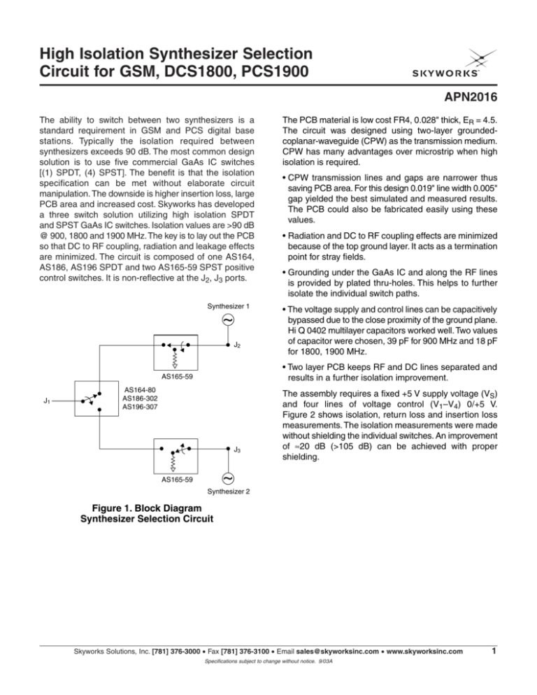
High Isolation Synthesizer Selection Circuit for GSM, DCS1800, PCS1900 APN2016 The ability to switch between two synthesizers is a standard requirement in GSM and PCS digital base stations. Typically the isolation required between synthesizers exceeds 90 dB. The most common design solution is to use five commercial GaAs IC switches [(1) SPDT, (4) SPST]. The benefit is that the isolation specification can be met without elaborate circuit manipulation. The downside is higher insertion loss, large PCB area and increased cost. Skyworks has developed a three switch solution utilizing high isolation SPDT and SPST GaAs IC switches. Isolation values are >90 dB @ 900, 1800 and 1900 MHz. The key is to lay out the PCB so that DC to RF coupling, radiation and leakage effects are minimized. The circuit is composed of one AS164, AS186, AS196 SPDT and two AS165-59 SPST positive control switches. It is non-reflective at the J2, J3 ports. Synthesizer 1 ~ J2 • CPW transmission lines and gaps are narrower thus saving PCB area. For this design 0.019" line width 0.005" gap yielded the best simulated and measured results. The PCB could also be fabricated easily using these values. • Radiation and DC to RF coupling effects are minimized because of the top ground layer. It acts as a termination point for stray fields. • Grounding under the GaAs IC and along the RF lines is provided by plated thru-holes. This helps to further isolate the individual switch paths. • The voltage supply and control lines can be capacitively bypassed due to the close proximity of the ground plane. Hi Q 0402 multilayer capacitors worked well. Two values of capacitor were chosen, 39 pF for 900 MHz and 18 pF for 1800, 1900 MHz. • Two layer PCB keeps RF and DC lines separated and results in a further isolation improvement. AS165-59 J1 The PCB material is low cost FR4, 0.028" thick, ER = 4.5. The circuit was designed using two-layer groundedcoplanar-waveguide (CPW) as the transmission medium. CPW has many advantages over microstrip when high isolation is required. AS164-80 AS186-302 AS196-307 J3 The assembly requires a fixed +5 V supply voltage (VS) and four lines of voltage control (V1–V4) 0/+5 V. Figure 2 shows isolation, return loss and insertion loss measurements. The isolation measurements were made without shielding the individual switches. An improvement of ≈20 dB (>105 dB) can be achieved with proper shielding. ~ AS165-59 Synthesizer 2 Figure 1. Block Diagram Synthesizer Selection Circuit Skyworks Solutions, Inc. [781] 376-3000 • Fax [781] 376-3100 • Email sales@skyworksinc.com • www.skyworksinc.com Specifications subject to change without notice. 9/03A 1 High Isolation Synthesizer Selection Circuit for GSM, DCS1800, PCS1900 -70 -16 -18 -80 -20 -90 -22 -100 -24 -26 -110 -28 -30 -120 0.5 1 1.5 2 -5 Return Loss (dB) -14 -1.2 -1.4 -10 -1.6 -15 -20 -1.8 -25 -2.0 -30 0.5 1 1.5 Frequency (GHz) Frequency (GHz) Synthesizer Switch Isolation & Return Loss Synthesizer Switch Insertion Loss & Return Loss 2 Figure 2. Isolation, Return Loss, Insertion Loss Measurements 2 Skyworks Solutions, Inc. [781] 376-3000 • Fax [781] 376-3100 • Email sales@skyworksinc.com • www.skyworksinc.com Specifications subject to change without notice. 9/03A Insertion Loss (dB) Isolation (dB) -60 0 Output Return Loss (dB) -10 -12 -50 APN2016
