DIFFERENCE BETWEEN LAYER 2 and LAYER 3 VPN in
advertisement
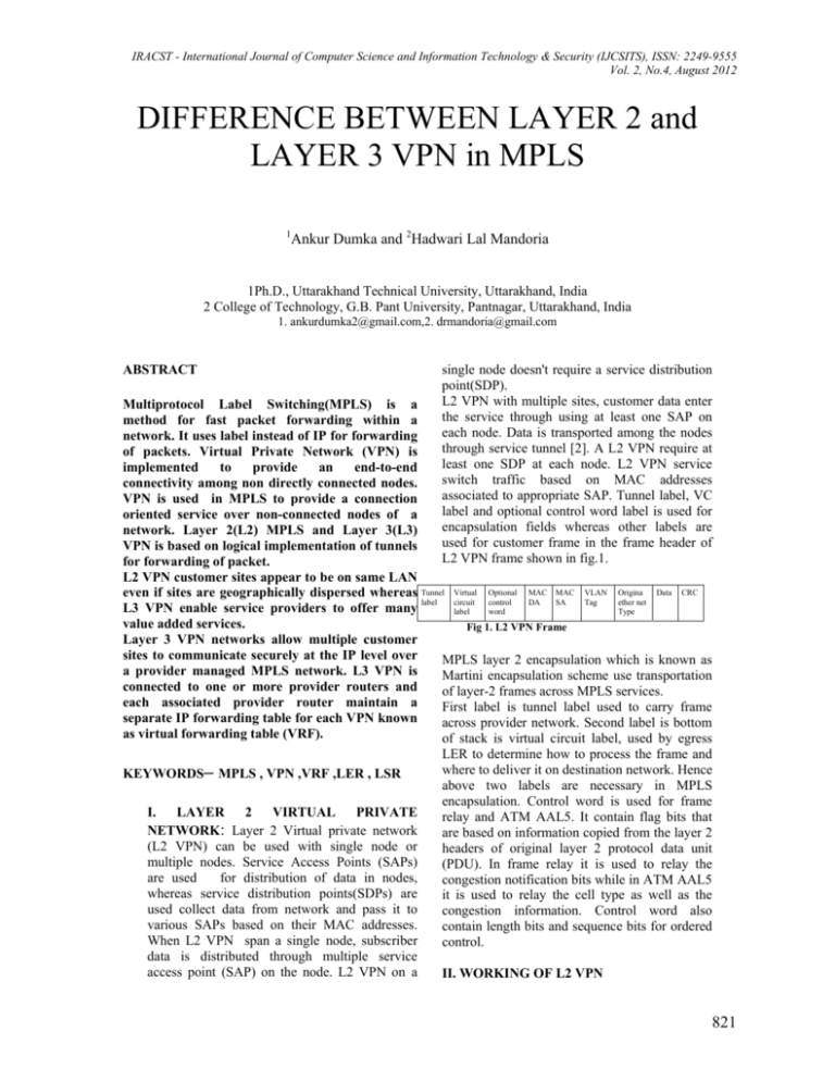
IRACST - International Journal of Computer Science and Information Technology & Security (IJCSITS), ISSN: 2249-9555 Vol. 2, No.4, August 2012 DIFFERENCE BETWEEN LAYER 2 and LAYER 3 VPN in MPLS 1 Ankur Dumka and 2Hadwari Lal Mandoria 1Ph.D., Uttarakhand Technical University, Uttarakhand, India 2 College of Technology, G.B. Pant University, Pantnagar, Uttarakhand, India 1. ankurdumka2@gmail.com,2. drmandoria@gmail.com ABSTRACT single node doesn't require a service distribution point(SDP). L2 VPN with multiple sites, customer data enter the service through using at least one SAP on each node. Data is transported among the nodes through service tunnel [2]. A L2 VPN require at least one SDP at each node. L2 VPN service switch traffic based on MAC addresses associated to appropriate SAP. Tunnel label, VC label and optional control word label is used for encapsulation fields whereas other labels are used for customer frame in the frame header of L2 VPN frame shown in fig.1. Multiprotocol Label Switching(MPLS) is a method for fast packet forwarding within a network. It uses label instead of IP for forwarding of packets. Virtual Private Network (VPN) is implemented to provide an end-to-end connectivity among non directly connected nodes. VPN is used in MPLS to provide a connection oriented service over non-connected nodes of a network. Layer 2(L2) MPLS and Layer 3(L3) VPN is based on logical implementation of tunnels for forwarding of packet. L2 VPN customer sites appear to be on same LAN even if sites are geographically dispersed whereas Tunnel Virtual Optional MAC MAC VLAN Origina Data CRC label circuit control DA SA Tag ether net L3 VPN enable service providers to offer many label word Type value added services. Fig 1. L2 VPN Frame Layer 3 VPN networks allow multiple customer sites to communicate securely at the IP level over MPLS layer 2 encapsulation which is known as a provider managed MPLS network. L3 VPN is Martini encapsulation scheme use transportation connected to one or more provider routers and of layer-2 frames across MPLS services. each associated provider router maintain a First label is tunnel label used to carry frame separate IP forwarding table for each VPN known across provider network. Second label is bottom as virtual forwarding table (VRF). of stack is virtual circuit label, used by egress LER to determine how to process the frame and where to deliver it on destination network. Hence KEYWORDS– MPLS , VPN ,VRF ,LER , LSR above two labels are necessary in MPLS encapsulation. Control word is used for frame I. LAYER 2 VIRTUAL PRIVATE relay and ATM AAL5. It contain flag bits that NETWORK: Layer 2 Virtual private network are based on information copied from the layer 2 (L2 VPN) can be used with single node or headers of original layer 2 protocol data unit multiple nodes. Service Access Points (SAPs) (PDU). In frame relay it is used to relay the are used for distribution of data in nodes, congestion notification bits while in ATM AAL5 whereas service distribution points(SDPs) are it is used to relay the cell type as well as the used collect data from network and pass it to congestion information. Control word also various SAPs based on their MAC addresses. contain length bits and sequence bits for ordered When L2 VPN span a single node, subscriber control. data is distributed through multiple service access point (SAP) on the node. L2 VPN on a II. WORKING OF L2 VPN 821 IRACST - International Journal of Computer Science and Information Technology & Security (IJCSITS), ISSN: 22499555 Vol. 2, No.4, August 2012 be bi-directional, a SDP must be provisioned on each node participating in the service. A service tunnel is used by SDP to direct traffic one router to another. SDPs uses the system IP address to identify far end destinations. SDP is not specific to one service; many services can use the same SDP. All services bound to an SDP use the same encapsulation as defined by that SDP(GRE or MPLS). The service tunnel is provisioned with an service requirement. Fig 2 Layer 2 VPN working of MPLS (single node) III. LAYER 3 VIRTUAL PRIVATE NETWORK Service access point (SAP) is a logical entity thatRFC 4364 describe a method to provide a layer 3 serve as customer access point to the services figVPN service by providing customers with 2 [5]. Each subscriber service is configured atfacilities[1] : 1.) distributing the customer’s routing least one SAP. A SAP can be configured on port information between sites configured as access port. SAP is local to the 2.) forwarding customer originated data packet router and is uniquely identified by physical to appropriate destination ethernet port or packet over SONET /SDH 3.) providing secure layer 3 routing (POS) port and channel, encapsulation type and connectivity between the various customer encapsulation identifier (ID) and it is provisioned sites on access port. Depending on encapsulation used, a physical port or POS, channel can have In L3 VPN there are customer edge devices that more than one SAP associated with it. Using act as an interface between customer and service dot1q encapsulation or POS channels, the router provider network. These customer edge devices can support multiple services for a customer or exchange routing information with other services for multiple customers. Whereas customer routers and provider routers at the same service distribution path (SDP) is a logically site by means of a common routing protocol . unique ID number and give the system address Provider edge devices known as Label Edge of originating and far end router. SDP is used for Routers (LER) act as an interface between directing traffic from one router to another customer edge and service provider networks, through unidirectional service tunnel. An SDP these devices are directly connected to customer originating on one node terminates at the edge devices. The provider edge devices destination node, which then directs incoming exchange provider core IP routing information packet to the correct service egress SAPs on that with other provider routers by means of a core node. protocol it also exchange customer routes (L3 VPN ) with other PEs by running a common routing protocol with other provider edge. Provider edge devices may be connected to one or more customer edge devices and its different ports may be part of same or different L3 VPN services. The provider routers known as Label Switch Router (LSR) which form the internal provider core network. These devices are connected to either other provider or provider edge routers. They exchange the routing information by means of IGP protocols. These routers are unaware of Fig. 3 Layer 2 VPN working of MPLS L3 VPNs. (multiple node) A multi node service fig. 3 needs at least one SAP and SDP on each node [5]. For a service to 822 IRACST - International Journal of Computer Science and Information Technology & Security (IJCSITS), ISSN: 22499555 Vol. 2, No.4, August 2012 There may be one or more MPLS label applied to any customer packet in the provider core in L3 VPN. Layer 2 LSP Label VPN Label IP Data Fig 5 MPLS label with L3 VPN L3 VPN services uses a label stack consisting of two labels as shown in fig 5. Outer label is known as top, LSP label and used to identify the transport tunnel between Provider Edges. The inner label is known as service or VPN label and identifies the customer VPN or service [3]. L3 VPN provides an end to end service between customer sites utilizing a transport tunnel between across a provider core Each provider edge router maintains separate logical routing table for each layer3 VPN, this table referred as VPN routing and forwarding (VRF). This table separately isolates the routing information of one customer from the next and also from routes of the provider core network. Each provider edge router may maintain a separate VRFs based on customer sites it connect to . L3 VPN functionality can be divided into two parts: 1.) control plane 2.) data plane Control plane function is to exchange the routing and label signaling information in the provider core. These function are handled by separate protocols, based on administrative distance. Second function of L3 VPN is to ensure customer integrity and security. The service provider is offering services to multiple customers and it must ensure that routing information for each customer is kept distinct and isolated and not exchanged with other router. Data plane function allows customer packets to flow between intended sites after previous two functions have been successfully implemented. The L3 VPN routing control plane provides the necessary exchange of routing information between devices aware of L3 VPN. Customer Edge routers maintains a standard IP routing table containing routes for L3 VPN to which it belongs. The label signaling control plane function of L3 VPN provides the necessary signaling to allow for the exchange of MPLS labels between all devices in the provider core. A transport tunnel is established based on these labels across the provider core to define the data path for customer packets between PEs. The data plane function of L3 VPN is the actual forwarding path across the provider network. The data plane forward data between customer sites. Customer data uses MPLS or GRE encapsulation, based on tunnel type in use. ROUTE DISTINGUISHER– Route distinguisher are used for global unique of IP prefixes. VPN IPv4 address is 12 byte composed of 8 byte of route distinguisher followed by 4 byte IPv4 address . The address structure allows multiple distinct routes for same IPV4 destination address to coexist as the addition of route distinguisher prefix to the IPV4 address ensure that is made unique. Route distinguisher consists of three fields : type, administrator(length) and assigned number (value). Type is 2 byte in length and length and value field combined to 6 byte, both are not fixed. Example - 54321:1 MULTIPROTOCOL BGP EXTENSION: BGP routing protocol is used to forward IP packet but discard VPN IPV4 packets for them multiprotocol BGP extension protocol is used. Separate address family are viewed as different protocols in MP-BGP. BGP EXTENDED COMMUNITIES : The BGP extended community attribute provide mechanism for including additional information to be carried in BGP updates [4]. There can be only one route distinguisher per route and there can be multiple route target per route . 823 IRACST - International Journal of Computer Science and Information Technology & Security (IJCSITS), ISSN: 22499555 Vol. 2, No.4, August 2012 IV. REFERENCES [1.] Lan jun and Lin bi ying, 2011 International Conference on Mechatronic Science, Electric Engineering and Computer, “Research for Service Deployment Based on MPLS L3 VPN Technology“,August 19-22, 2011, Jilin, China page 14841488. [2.] Rahul Aggarwal, Juniper Networks, OAM Mechanisms in MPLS Layer 2 Transport Networks, IEEEcommunication magazine october 2004 , page 124-130. [3.]Yoo-Hwa Kang, and Jong-Hyup Lee, “The Implementation of the Premium Services for MPLS IP VPNs”Advanced Communication Technology, 2005, ICACT 2005. The 7th International Conference on Volume: 2 Digital Object Identifier: 10.1109/ICACT.2005.246152 ,Publication Year: 2005 , Page(s): 1107 - 1110 [4.] R. Boutaba ,W. Szeto and Y.Iraqi,”, Emerging Trends in Engineering and Technology, 2008. ICETET '08. First International Conference on Digital Object Identifier: 10.1109/ICETET.2008.58 Publication Year: 2008 , Page(s): 187 – 192. [5]“www.cisco.com/en/US/docs/internetworking/technology/ MPLS/VPN/handbook“from Cisco recognized site available. 824
