INSTRUCTION SHEET - Installation of Wire “Reel” or “Spool” on the
advertisement
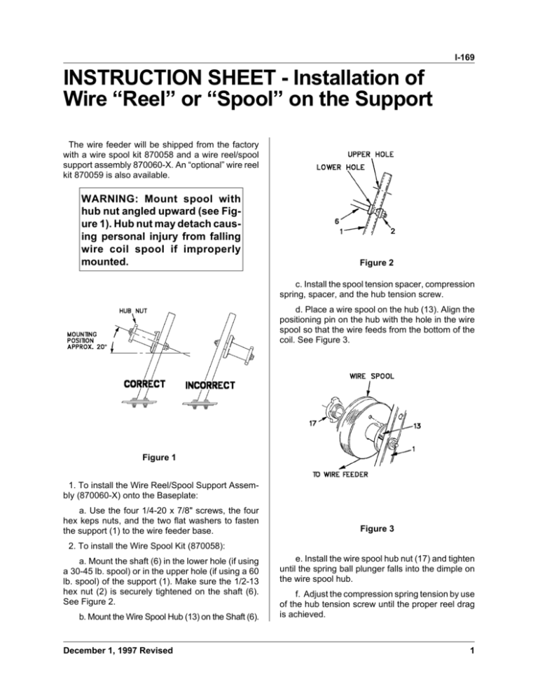
I-169 INSTRUCTION SHEET - Installation of Wire “Reel” or “Spool” on the Support The wire feeder will be shipped from the factory with a wire spool kit 870058 and a wire reel/spool support assembly 870060-X. An “optional” wire reel kit 870059 is also available. WARNING: Mount spool with hub nut angled upward (see Figure 1). Hub nut may detach causing personal injury from falling wire coil spool if improperly mounted. Figure 2 c. Install the spool tension spacer, compression spring, spacer, and the hub tension screw. d. Place a wire spool on the hub (13). Align the positioning pin on the hub with the hole in the wire spool so that the wire feeds from the bottom of the coil. See Figure 3. Figure 1 1. To install the Wire Reel/Spool Support Assembly (870060-X) onto the Baseplate: a. Use the four 1/4-20 x 7/8" screws, the four hex keps nuts, and the two flat washers to fasten the support (1) to the wire feeder base. Figure 3 2. To install the Wire Spool Kit (870058): a. Mount the shaft (6) in the lower hole (if using a 30-45 lb. spool) or in the upper hole (if using a 60 lb. spool) of the support (1). Make sure the 1/2-13 hex nut (2) is securely tightened on the shaft (6). See Figure 2. b. Mount the Wire Spool Hub (13) on the Shaft (6). December 1, 1997 Revised e. Install the wire spool hub nut (17) and tighten until the spring ball plunger falls into the dimple on the wire spool hub. f. Adjust the compression spring tension by use of the hub tension screw until the proper reel drag is achieved. 1 I-169 Figure 4 3. To install the Wire Reel Kit (870059): a. Mount the shaft (6) in the upper hole of the support (1) to assure proper clearance for the wire reel (7). See Figure 4. b. Mount the wire reel (7) on the shaft (6). c. Install the wire reel washer, the steel wire reel washer, compression spring, “T” wire reel washer, and the drag adjusting screw. 2 Figure 5 d. Loosen the wing nuts holding the movable arms. Rotate the arms inward towards the center of the reel (7). Place the coiled wire on the reel so the wire feeds from the bottom of the coil to the wire feeder. See Figure 5. e. Reposition the movable arms outward and tighten the wing nuts. f. Tighten the drag adjusting screw until the desired reel drag is achieved. December 1, 1997 Revised I-169 December 1, 1997 Revised 3 I-169 This page intentionally left blank. 4 December 1, 1997 Revised I-169 December 1, 1997 Revised 5 I-169 This page intentionally left blank. 6 December 1, 1997 Revised I-169 December 1, 1997 Revised 7 I-169 This page intentionally left blank. 8 December 1, 1997 Revised
