Experiment #10, Diffraction and Quantized Transitions
Physics 182 – Fall 2014 – Experiment #10 1
Experiment #10, Diffraction and Quantized Transitions
1 Purpose
In this experiment we will be using a diffraction grating spectrometer to analyze the spectrum of light produced in a Hydrogen discharge tube. The spectrometer uses the constructive interference produced by waves of light to separate the colors emitted by the gas. The gas produces light at certain specific wavelengths when electrons in the molecules transition between quantized energy states. The spectrometer allows us to quantitatively measure the wavelength of the light produced, and as a consequence, measure the energy of the states the electrons inhabit in the molecule
2 Introduction
This lab uses a technique that depends on the wave nature of light to measure the quantized energy states for electrons in Hydrogen. Historically, this measurement of the so called Balmer Series of spectral lines was one of the first problems solved by Neils
Bohr’s theory of Quantum Mechanics. Experimentally, this technique is fundamental for the understanding of the properties of new molecules synthesized by chemists. In
Astrophysics we measure the spectral lines in the light emitted by distant stars to understand their chemical composition and the nuclear reactions that are occurring inside them. Closer to home, if you want to know what the gasses that are emitted from the tail pipe of a car are, so that you can control air pollution, you measure the spectrums of the gasses in the exhaust.
3 Background
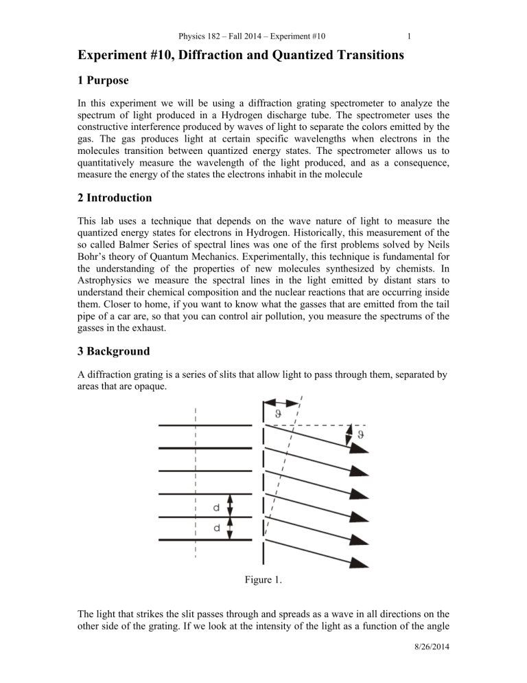
A diffraction grating is a series of slits that allow light to pass through them, separated by areas that are opaque.
Figure 1.
The light that strikes the slit passes through and spreads as a wave in all directions on the other side of the grating. If we look at the intensity of the light as a function of the angle
8/26/2014
2 away from the line normal to the grating we will notice that there are certain angles where the intensity of a particular color is high, like the spreading of colors after passing a beam of light through a prism. The increase in intensity occurs when the distance between successive slits on the grating and the point at which the intensity is measured differs by an integer number of wavelengths. The difference in distance between two slits is,
Δ
l dSin( )
(1) where d is the distance between slits. This gives us the criterion for maximum brightness,
Sin( ) m
λ
(2) d where
is the wavelength of the light and m is an integer (m = 1, 2, 3…). For a grating with a known line separation, d , we can determine the wavelength of light at the intensity maximum by measuring the angle at which that maximum occurs.
The energy of electronic states in an atom is quantized. Neils Bohr showed that the binding energy for an electron in an orbital around a Hydrogen atom has the form,
E n
13 .
6 eV n
2
, where n = 1, 2, 3… (3)
Transitions between these allowed atomic orbitals emit light with characteristic frequencies determined by the difference in energy between the initial and final states, hv
E ni
E nf
13 .
6
1 n
2 f
1 n i
2 eV , (4) where n f
is the integer describing the final state, n i
is the integer describing the initial state, h is Plank’s constant ( h = 4.1357 X 10
-15
eV-sec), and
is the frequency of the light emitted. Since the wavelength of the light is related to its frequency and the speed of light by the relationship,
c
, (5) we can find series of lines describing sets of transitions with common final states. For example, the famous Balmer series has n f
= 2. Solving for 1/
, we get,
1
R
2
1
2
1 n
2
(6) where n is an integer greater than 2 and R = 1.0968 X 10
7
m
-1
. The Balmer series is particularly well studied since it has lines that are visible to the human eye. In this experiment you will be measuring three lines in the Balmer series and determining the constant R , verifying Bohr’s prediction for the atomic spectrum of Hydrogen.
Physics 182 – Fall 2014 – Experiment #10 3
The lines you will be measuring are;
H :
1
R
1
2
2
1
3
2
------ red
H :
1
R
1
2
2
1
4
2
------ blue-green (7)
H :
1
R
2
1
2
1
5
2
------ blue-violet
The measurement apparatus is shown below. There is a text book image of a spectrometer and a schematic diagram to indicate how
is defined.
Experimental Apparatus.
8/26/2014
4
(Schematic of Apparatus)
4 Procedure
First; a few warnings; a) Don’t touch the diffraction grating on the spectrometer. This measurement is quite sensitive to the alignment of the grating. If you compromise the alignment you will have difficulty making good measurements b) For the same reason, don’t rotate the spectrometer arm by the eyepiece. This may rotate the crosshair. c) The lamps emit ultra-violet light. Staring at them is bad for your eyes. You are protected by the glass in the lenses of the spectrometer telescope; so, you are OK if you are looking at the spectrum lines, but try to not look directly at the tube. d) Let your TA switch tubes for you.
OK. The measurement breaks down into two parts. First you will use a line from the spectrum of Helium to determine ‘ d ’ for your spectrometer grating. Then you will use your calibrated grating to measure lines from the Hydrogen spectrum and determine the
Rydberg constant, R .
1) With the Helium lamp mounted, move the telescope arm so that it is in line with the collimating tube. Looking through the telescope, adjust the position of the telescope arm until you see the undiffracted light coming through the slit on the collimator. This should correspond to a reading of approximately
180 degrees. This is the center point of the spectrometer. Adjust the position until the vertical crosshair is aligned with the right hand edge of the slit and record the position in both degrees and minutes of the angle (You will need to read the vernier for the minutes, if you have trouble with this ask the TA. You
Physics 182 – Fall 2014 – Experiment #10 5 will need to convert Minutes of Arc to degrees. There are 60 minutes in 1 degree; so, 6 Minutes of Arc is 0.1 degrees.). This 180 degree center point comes from setting up the spectrometer. It has nothing to do with the sum of two angles divided by 2 equaling 180 degrees which you will read about soon.
2) Now, rotate the telescope away from the center point. You should see a sequence of lines; purple, green, yellow and red. They should appear within
12.5° on both sides of the spectrometer. All measurements will be made by taking data from both sides. If you continue beyond 12.5° you will find that the sequence of lines repeats. These “higher order” diffraction peaks occur when the distance difference between two successive slits on the diffraction grating and the measurement point differs by 2 or 3 or 4 wavelengths. We will be confining our measurements to the primary (first order m = 1) diffraction maximum, but by using data from all of the available peaks you can do a statistical analysis to improve your measurements.
3) Now we want to determine the angle of diffraction for the yellow line in the spectrum of Helium. Move the telescope to the first yellow line on the left side so that the yellow line is centered on the crosshair. Align the crosshair with the right side of the yellow slit image. Record the position in degrees and minutes (around 190 degrees). Move the telescope arm over to the first yellow line on the right hand side of the spectrometer (passing through the center point) so that the yellow line is centered. Measure the position of the yellow line on the right side by aligning the crosshair, once again, with the right side of the slit image. Record the position in degrees and minutes (around 170 degrees). The sum of these two angles divided by 2 should equal 180 degrees.
Note that
L results for (
L
+
+
R
should equal 360 degrees. Use percent error to compare
R
)/2 with the accepted value of 180 degrees.
4) If the sum of these two angles divided by 2 compares favorably with 180 degrees, take the difference in your left and right measurements,
divide by 2. This is your measurement of the angular position
L
-
yellow
R
, and
of the diffraction maximum for the first order yellow line in the Helium spectrum.
Have your TA switch you to the Hydrogen lamp at this point. You will want to let it warm up for a few minutes.
5) Use the results of step 4 to calculate d for your spectrometer’s grating and the separation of slits on your diffraction grating. These gratings have a nominal specification of 3000 lines per centimeter.
6) Using the spectrometer measure the left and right angles of the Balmer lines at their primary diffraction maximums; blue-violet, blue-green and red. Again, align the crosshair with the right hand edge of the slit. For each color, be sure to use percent error to compare results for (
L
+
R
)/2 with the accepted value of 180 degrees.
7) Use your data from part 6 to calculate the wavelengths of these three lines
(colors) in the hydrogen spectrum.
8/26/2014
6
5. Calculations and Analysis (With Data Sheet Included.)
(Your lab report should have a separate data section.)
Calculation of Center Point, Part 1 (data and calculations);
Degrees ° and Minutes ’
center
(°,’)
Degrees
center
(xxx.xx°)
Calculation of the angle of diffraction for the Helium yellow line, Parts 3, 4 and 5;
Measurement of Helium Line (data and calculations);
L
(°,’)
L
(xxx.xx°)
R
(°,’)
R
(xxx.xx°) (
L
+
R
)/2 (
L
–
R
)/2
1) Calculate the percent error between the accepted value of 180 degrees and the calculated average value of (
L
+
decimal point when calculating (
L
R
)/2. (Use at least three numbers after the
+
R
)/2.) yellow
is given by (
L
–
R
)/2. This is the diffraction maximum for the primary, first order (m = 1), yellow line. (Use at least three numbers after decimal point for this calculation.)
3) The wavelength of the yellow line of Helium is,
= 5875.6 Å. Use Equation
(2) and
yellow
to determine , in Ångstroms , the spacing of slits, d , on your grating. Note: 1 Å = 1x10
-10
meters. (Example calculation d = 33201.09 Å)
4) Calculate how many slits there are per centimeter (1/d) on your grating. Use percent error to compare your experimental value to the accepted value of
3000 lines per centimeter. (Example calculation 1/d = 3011.95 lines/cm)
Hydrogen calculations, Parts 6 and 7;
Hydrogen Measurements (data and calculations);
Line
Blue-Violet
Blue-Green
L
(°,’)
Red
L
(xxx.xx°)
R
(°,’)
R
(xxx.xx°) (
L
+
R
)/2
1) Calculate the average (mean), standard deviation (s) and standard deviation of the mean (SDM) using the three calculations of (
L
+
R
)/2. These values should have three numbers after the decimal point. Calculate the percent error of the average value using 180 degrees as the accepted value.
Average value of (
L
+
R
)/2 = _________________ s = ________________ SDM = ________________ % error = ________________
2)
L and
R in the above table should be entered into the table below.
Physics 182 – Fall 2014 – Experiment #10 7
Hydrogen Analysis (data and calculations);
Line
Blue-Violet
L
(xxx.xx°)
R
(xxx.xx°) (
L
–
R
)/2
Blue-Green
Red
Å) R (m
-1
)
1) Take your data from the above table and your calculation of d , and use
Equation (2), to calculate the wavelengths of the three Balmer Series lines you have measured. (Example answer form
= 4340.5 Å.)
2) Use percent error to compare the accepted values of
(4340.5
Å , 4861.3
Å and 6562.9
Å ) to your experimental values.
3) For each line determine an experimental value of the Rydberg constant, R , which appears in Equations (6) and (7).
It is suggested that scientific notation should be used for this calculation, with at least four numbers after the decimal point for the average value. Excel and calculators can be set to do calculations in this mode. (Example answer form R = 1.0971 X 10
7
m
-1
.)
4) Using your three values of R , calculate the average experimental value of R .
5) Use percent error to compare your average value of R to the accepted
(theoretical) value of R = 1.0968 X 10
7
m
-1
.
6. Questions
1) Calculate the wavelength of the n = 7 line in the Balmer series. Why don’t you see this line in the spectrometer?
2) Assume that we use a Helium-Neon laser as a light source instead of the
Hydrogen discharge tube. Assuming the wavelength coming out of the laser is
6328 Å, at what angle would you expect to see the primary diffraction maximum?
3) How would the grating equation change if the incident light beam was not perpendicular to the grating? Could you see evidence of this misalignment in your measurement?
4) Why does the central undiffracted light have the same color as the Hydrogen discharge tube?
7. Discussion
In this open response section of the lab report you have the opportunity to demonstrate that you have gained a comprehensive understanding of all aspects of the experiment. In your own analysis, what were the key elements of the experimental measurement? Are the results intuitive or do they appear in any way to be inconsistent with physical observations in daily life? Are there intrinsic aspects of either the experimental design or the way it was implemented that could introduce systematic errors or fail to account for relevant physical phenomena? A detailed discussion should include analysis of any experimental errors, instrumentation problems or mishaps that occurred, and how these may have impacted the results. Be thoughtful and think critically about these considerations. If an experiment was challenging, a discussion of exactly what made it
8/26/2014
8 challenging, and possibly, how it could be conducted differently, should be included. Or, if an experimental measurement went completely smoothly, this should also be discussed.
Also this section may include discussion of how the insights from one particular experiment are related or complementary to other experiments conducted in the course.
Remember that your discussion should be a thoughtful scientific analysis, not a discussion of how you enjoyed or did not enjoy the lab.
8. Conclusions
The report should end with a clear conclusion statement. This is the “bottom-line” experimental result summarizing the main quantitative results of the experiment and the extent to which they are in agreement with theoretical predication and/or an established reference value. When the experiment results in a measurement of a constant (e.g., the acceleration due to gravity at the earth’s surface), compare it with its established handbook values for the Boston area. Use percent error to quantify this comparison. To make this comparison meaningful, you should include the impact of the experimental error (random, systematic and any individual investigator mistakes) on your results. This includes errors in plotting and reading linear graphs when determining their slope and intercept.
Your conclusion should include an explicit calculation of the Rydberg constant from your data. How does your measured values of the Rydberg constant compare with the value given in the handout? How do your three measured values deviate from this value? Is your error systematic, random or a combination of the two? Are differences between your measured values of (
L
+
R
)/2 and the accepted value of 180 degrees significant in your calculations of the Rydberg constant? Consider other possible sources of error.

