Ajay Joshi, Fred Chen and Vladimir Stojanović Department of EECS
advertisement
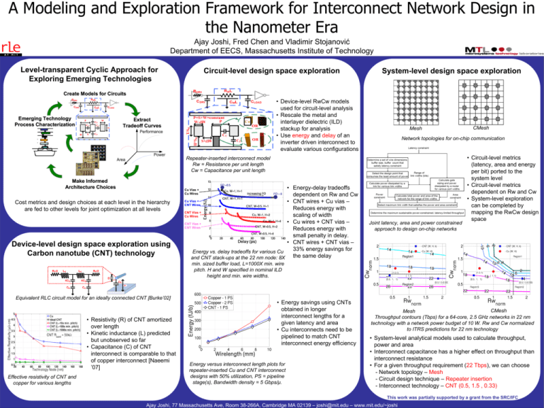
A Modeling and Exploration Framework for Interconnect Network Design in the Nanometer Era Ajay Joshi, Fred Chen and Vladimir Stojanović Department of EECS, Massachusetts Institute of Technology Level-transparent Cyclic Approach for Exploring Emerging Technologies Circuit-level design space exploration System-level design space exploration Create Models for Circuits • Device-level RwCw models used for circuit-level analysis • Rescale the metal and interlayer dielectric (ILD) stackup for analysis • Use energy and delay of an inverter driven interconnect to evaluate various configurations RWL CDRV CLOAD CWL Emerging Technology Process Characterization P H CC S CP CC W T RDRV Extract Tradeoff Curves CP Mesh Network topologies for on-chip communication Repeater-inserted interconnect model Rw = Resistance per unit length Cw = Capacitance per unit length Make Informed Architecture Choices • Energy-delay tradeoffs dependent on Rw and Cw Cu Vias + • CNT wires + Cu vias – CNT Wires Reduces energy with CNT Vias + scaling of width Cu Wires • Cu wires + CNT vias – CNT Vias + CNT Wires Reduces energy with small penalty in delay. • CNT wires + CNT vias – 33% energy savings for Energy vs. delay tradeoffs for various Cu the same delay and CNT stack-ups at the 22 nm node: 8X Cu Vias + Cu Wires Cost metrics and design choices at each level in the hierarchy are fed to other levels for joint optimization at all levels Device-level design space exploration using Carbon nanotube (CNT) technology CMesh Joint latency, area and power constrained approach to design on-chip networks • Circuit-level metrics (latency, area and energy per bit) ported to the system level • Circuit-level metrics dependent on Rw and Cw • System-level exploration can be completed by mapping the RwCw design space min. sized buffer load, L=1000X min. wire pitch. H and W specified in nominal ILD height and min. wire widths. Equivalent RLC circuit model for an ideally connected CNT [Burke’02] • Resistivity (R) of CNT amortized over length • Kinetic inductance (L) predicted but unobserved so far • Capacitance (C) of CNT interconnect is comparable to that of copper interconnect [Naeemi ’07] Effective resistivity of CNT and copper for various lengths • Energy savings using CNTs obtained in longer interconnect lengths for a given latency and area • Cu interconnects need to be pipelined to match CNT interconnect energy efficiency Energy versus interconnect length plots for repeater-inserted Cu and CNT interconnect designs with 50% utilization, PS = pipeline stage(s), Bandwidth density = 5 Gbps/μ. CMesh Mesh Throughput contours (Tbps) for a 64-core, 2.5 GHz networks in 22 nm technology with a network power budget of 10 W. Rw and Cw normalized to ITRS predictions for 22 nm technology • System-level analytical models used to calculate throughput, power and area • Interconnect capacitance has a higher effect on throughput than interconnect resistance • For a given throughput requirement (22 Tbps), we can choose - Network topology – Mesh - Circuit design technique – Repeater insertion - Interconnect technology – CNT (0.5, 1.5 , 0.33) This work was partially supported by a grant from the SRC/IFC Ajay Joshi, 77 Massachusetts Ave, Room 38-266A, Cambridge MA 02139 – joshi@mit.edu – www.mit.edu/~joshi

