Double-Rodded Double Rodded Leveling
advertisement
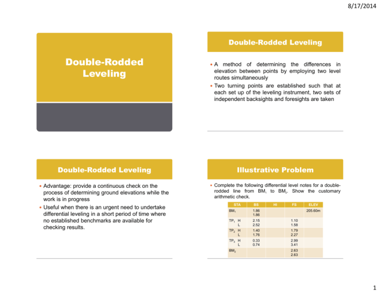
8/17/2014 Double-Rodded Leveling Double-Rodded Double Rodded Leveling A method of determining the differences in elevation between points by employing two level routes simultaneously Two turning points are established such that at each set up of the leveling instrument, two sets of independent backsights and foresights are taken Double-Rodded Leveling Advantage: provide a continuous check on the process of determining ground elevations while the work is in progress Useful when there is an urgent need to undertake differential leveling in a short period of time where no established benchmarks are available for checking results results. Illustrative Problem Complete the following differential level notes for a double- rodded line from BM1 to BM2. Show the customary arithmetic check. STA BS HI FS BM1 1.86 1.86 TP1 H L 2.15 2.52 1.10 1.58 TP2 H L 1.40 1.76 1.79 2.27 TP3 H L 0.33 0.74 2.99 3.41 BM2 ELEV 205.60m 2.63 2.63 1 8/17/2014 Illustrative Problem Arithmetic Check 1st Method • Mean Elev BM2 = 2nd Method • Mean Elev BM2 = BM1 + [(ΣBS-ΣFS)/2] • DE1 = (ΣBS-ΣFS)/2 Three-Wire Leveling • DE2 = BM1 – Mean Elev BM2 Three-Wire Leveling More p precise method Method of determining the differences in elevation wherein three horizontal hairs are read and recorded rather than from a single horizontal hair Any level equipped with three horizontal cross g hairs can be used for three-wire leveling Three-Wire Leveling s = a-b m = (a (a+b+c)/3 b c)/3 HD = Ks + C Elev = HI - m a = upper stadia hair reading b = lower stadia hair reading c = horizontal cross hair reading s = stadia intercept - difference diff b between t th the upper and lower stadia hair reading m = mean of the three-hair readings HD = horizontal distance from the level to the rod K = stadia interval factor (100) C = instrument constant (0) 2 8/17/2014 Illustrative Problem BACKSIGHT STA HAIR RDGS MEAN RDG FORESIGHT S HI HAIR RDGS MEAN RDG S ELEV Arithmetic Check 1st Method • DE1 = (ΣBSm-ΣFSm)/2 BM1 1.15 0.95 0.72 TP1 2.79 2.42 2.06 1.11 0.89 0.68 TP2 1.70 1 44 1.44 1.18 1.90 1 54 1.54 1.17 TP3 2.59 2.10 1.59 1.45 1.18 0.95 BM2 Illustrative Problem 2nd Method • Elev BM2 = BM1 + ΣBS - ΣFS 445.20 • DE2 = Elev BM1 – Elev BM2 1.60 1.35 1.25 Profile Leveling P fil L Profile Leveling li The process of determining differences in elevation along a fixed line at designated short measured intervals Design and construction of roads, railroads, canals, culverts, bridges, sewer lines (horizontal structures) Usually taken along the centerline with the level set up a convenient distance away from it so that sights of more uniform lengths can be obtained 3 8/17/2014 Profile Leveling Any number of foresights can be taken Intermediate I t di t foresights f i ht are taken t k where h necessary to t portray accurately the existing ground surface along the route surveyed Profile Leveling Profile A curved line which graphically portrays the intersection of a vertical plane with the surface of the earth Represent the ground elevations of selected critical points along a surveyed line and the horizontal distances between these points Stationing A numerical designation given in terms of horizontal distance any point along a profile line is away from the starting point Profile Leveling Illustrative Problem Intermediate foresights (ground rod readings) Taken along the centerline of the proposed project to provide an accurate representation of the ground surface A schematic arrangement of a profile level route from BM3 to BM4 Full stations Points which are established along the profile level route at uniformly measured distances Plus stations Points established along a profile level route which is not designated as a full station Points taken at breaks in the ground surface slope and at critical points (location of culverts, bridges) are shown below. The values indicated represent p backsight, g , foresight, and intermediate foresight readings taken on stations along the route. Prepare and complete profile level notes for the portrayed information. Show the customary arithmetic check and plot the profile. 2+00 HI 1+00 2 3+00 0+00 BM4 TP1 HI1 4+50 5+50 6+70 6+00 BM3 Elev 300.50m 4 8/17/2014 Illustrative Problem Illustrative Problem 303 BM3 BS HI FS IFS 2.4 300.50m 0+00 1.5 1+00 2.0 2+00 1.3 3+00 0.7 TP1 2.55 3.2 4+50 2.8 5+50 3.5 6+00 4.5 6+70 3.95 BM4 ELEV 302 ELEVATION (m) E STA 301 300 299 3.3 298 0+00 1+00 2+00 STATIONINGS 3+00 4+00 Illustrative Problem Arithmetic Check • Elev BM4 = BM3 + ΣBS - ΣFS Reciprocal Leveling 5 8/17/2014 Reciprocal Leveling Employed to determine the difference in elevation between two points when it is difficult or impossible to keep backsights and foresights short and equal Such conditions are running a line of levels across wide rivers, lakes, and rugged terrain (deep canyons) Two sets of rod readings are observed (Method of Reversion) Reciprocal Leveling Errors due to refraction by the atmosphere, curvature of the earth and faulty adjustment of the instrument are significantly reduced if not eliminated One set taken with the instrument set up close to one point and another instrument on the other Reciprocal Leveling Illustrative Problem In leveling across a deep and wide river, reciprocal level DE 1 a b DE2 a 'b' Instrumental errors and the effect of curvature and refraction DE1 ≠ DE2, » » TDE *Note: DE 1 DE2 (a b) (a 'b' ) 2 2 readings were taken between two points, X and Y as follows: a. With instrument set up near X, the rod readings on X are 1.27 and 1.265 meters; on the distant point Y, the rod readings are 2.50, 2.52, 2.55, and 2.49 meters. b. With instrument set up near Y, the rod readings on Y are 3 48 and 3.47 3.48 3 47 meters; on the distant point X X, the rod readings are 2.13, 2.14, and 2.145 meters. Determine the true difference in elevation between the two points and the elevation of Y if the known elevation of X is 289.90meters. If TDE is negative, A is higher than B; If TDE is positive, B is higher than A. 6 8/17/2014 Illustrative Problem Elev=289.90m T i Trigonometric t i Leveling L li Instrument Set up near X STA BS X 1.27 FS Instrument Set up near Y STA BS X’ 2.13 1.265 Y FS 2.14 2.50 2 50 2.52 2.145 Y’ 2.55 2.49 SUM 3.48 3.47 SUM MEAN MEAN Trigonometric Leveling Trigonometric Leveling “Indirect Leveling” Determine D t i th the diff difference iin elevation l ti ffrom observed vertical angle and either horizontal or inclined distances Used extensively when undertaking topographic surveys over rugged or rolling terrain since it provides a rapid means of determining vertical distances and elevation of points V dTan V sSin DEab dTan HI RR DEab sSin HI RR ElevB ElevA DEab 7 8/17/2014 Trigonometric Leveling Illustrative Problem For horizontal distance is greater than 300 meters, A vertical angle of +13°45’ is read to a target effects of the earth’s earth s curvature and refraction must be considered in the calculation of the vertical distances. d 2 DEab dTan HI RR 0.0675( ) 1000 d 2 DEab sSin HI RR 0.0675( ) 1000 1.23m 1 23m above point B. B the measured inclined distance, s, is 823.29m and the elevation of A is 123.65m above datum. If the HI at A is 1.35m, determine the difference in elevation between A and B and the elevation of B, considering the p refraction. effects of curvature and atmospheric Illustrative Problem Cross-Section Leveling 8 8/17/2014 CROSS-SECTION LEVELING Short profiles taken perpendicular to the centerline of projects such as a highway highway, railroad railroad, irrigation canal, or sewer line They may also be taken for borrow pits and excavations required for buildings, structures, and quarries. Roadway Cross-Sections Borrow-Pit Cross Sections ROADWAY CROSS-SECTION This type of cross-section is required for most route projects such as roads and railroads. Elevations of ground points along the section are taken at regular intervals on either side side. Where significant changes occur in ground features, ground elevations are also taken. BORROW-PIT CROSS-SECTION Employed in the construction of structures and buildings, and in the excavation of borrow pits. Borrow pit is an open area which is usually adjacent to a construction project where suitable fill material is excavated. The base line from which the GL are referred should be established outside the immediate project area so that reference stakes and other markers will not be obliterated or disturbed during the process of excavation. Similarly, any reference bench mark should also be located outside the work area. 9
