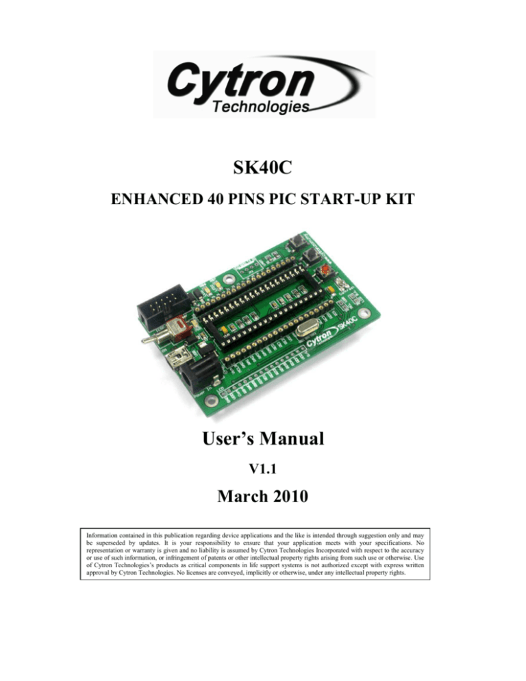
SK40C
ENHANCED 40 PINS PIC START-UP KIT
User’s Manual
V1.1
March 2010
Information contained in this publication regarding device applications and the like is intended through suggestion only and may
be superseded by updates. It is your responsibility to ensure that your application meets with your specifications. No
representation or warranty is given and no liability is assumed by Cytron Technologies Incorporated with respect to the accuracy
or use of such information, or infringement of patents or other intellectual property rights arising from such use or otherwise. Use
of Cytron Technologies’s products as critical components in life support systems is not authorized except with express written
approval by Cytron Technologies. No licenses are conveyed, implicitly or otherwise, under any intellectual property rights.
ROBOT . HEAD to TOE
Product User’s Manual – SK40C
Index
1. Introduction and Overview
2
2. Packing List
4
3. Board Layout
5
4. Product Specification
10
5. Installation (hardware)
11
5.1 Loading Program Using UIC00A Programmer
11
5.2 I/O Port (to electronic components)
13
5.3 UART Interface
18
5.4 USB Interface
21
5.4.1 SK40C USB
21
5.4.2 SK40C HID USB Bootloader
23
6. Getting Started
24
6.1 I/O Port (to electronic components)
24
6.2 UART
26
6.3 USB
35
7. Warranty
43
Appendix A (schematic)
44
Created by Cytron Technologies Sdn. Bhd. – All Rights Reserved
1
ROBOT . HEAD to TOE
Product User’s Manual – SK40C
1. INTRODUCTION AND OVERVIEW
SK40C is another enhanced version of 40 pins PIC microcontroller start up kit. It is designed
to offer an easy to start board for PIC MCU user. However, all interface and program should
be developed by user. This board comes with basic element for user to begin project
development. It offer plug and use features. This kit is designed to offer:
•
Industrial grade PCB
•
Every board is being fully tested before shipped to customer
•
Compact, powerful, flexible and robust start-up platform
•
Suitable for hobbyists and experts
•
Save development and soldering time
•
No extra components required for the PIC to function
•
All 33 I/O pins are nicely labeled to avoid miss-connection by users
•
Connector for UIC00A (low cost USB ICSP PIC Programmer) - simple and fast
method to load program
•
Fully compatible with SK40B
•
No more frustrated work plugging PIC out and back for re-programming
•
Perfectly fit for 40 pins 16F and PIC18F PIC
•
With UIC00A, program can be loaded in less than 5 seconds
•
More convenient to use and it is smaller than SK40B.
•
Maximum current is 1A.
•
Dimension: 85mm x 55mm
SK40C come with additional features:
•
2 x Programmable switch
•
2 x LED indicator
•
Turn pin for crystal. User may use others crystal provided.
•
LCD display (optional)
•
UART communication
•
USB on board.
•
And all the necessities to eliminate users difficulty in using PIC
Created by Cytron Technologies Sdn. Bhd. – All Rights Reserved
2
ROBOT . HEAD to TOE
Product User’s Manual – SK40C
Users are able to utilize the function of PIC by directly plugging in the I/O components in
whatever way that is convenient to user. With UIC00A connector on board, user can start
developing projects and have fun with this kit right away. This kit comes WITHOUT PIC
microcontroller to provide the freedom for user to choose PIC type.
This document explains the method to use SK40C.
Created by Cytron Technologies Sdn. Bhd. – All Rights Reserved
3
ROBOT . HEAD to TOE
Product User’s Manual – SK40C
2. PACKING LIST
Please check the parts and components according to the packing list. If there are any parts
missing, please contact us at sales@cytron.com.my immediately.
1. 1 x SK40C board with all components shown soldered
2. 1 x 16 Header pin for LCD Display.
3. 1 x 20M Hz Crystal
4. PIC MCU – Not included, please purchase separately from Cytron website
5. USB Cable – Not included, please purchase separately from Cytron website
6. UIC00A – Not included, please purchase separately from Cytron website
7. User Manual – Not included, please download from Cytron website
Created by Cytron Technologies Sdn. Bhd. – All Rights Reserved
4
ROBOT . HEAD to TOE
Product User’s Manual – SK40C
3. BOARD LAYOUT
E
H
F
I
G
C
D
J
B
N
K
A
M
L
O
P
a) Top View
Pin 1
of PIC
b) Side view
Created by Cytron Technologies Sdn. Bhd. – All Rights Reserved
5
ROBOT . HEAD to TOE
Product User’s Manual – SK40C
c) Bottom view
Label Function
Label
Function
A
DC power adaptor socket
I
Programmable Push Button
B
USB Connector
J
Reset button
C
Toggle Switch for power supply
K
LCD contrast
D
Power indicator LED
L
JP8 for LCD Backlight
M
JP9 for USB
E
Connector for UIC00A
Programmer
F
LED Indicator
N
40 pin IC socket for PIC MCU
G
Header pin and turn pin
O
Turn pin for crystal
H
UART Connector
P
LCD Display
A – DC power adaptor socket for user to plug in DC adaptor. The input voltage should be
ranged from 7 to 15V.
B – USB connector for communication between devices and a host controller (usually
personal computers). This function is only valid for certain model of PIC microcontroller.
Please refer to USB interface section. The power LED will light ON when the USB cable is
connected.
Created by Cytron Technologies Sdn. Bhd. – All Rights Reserved
6
ROBOT . HEAD to TOE
Product User’s Manual – SK40C
C – Toggle switch to On/Off the power supply from DC adaptor.
D – Power indicator LED for on board. It will light ON as long as the input power is correctly
connected.
E – 2x5 box header for UIC00A, USB ICSP PIC Programmer.
F – 2 LEDs (connected to RB6 and RB7) as active High output for PIC MCU. These LEDs
are controllable from PIC MCU.
G – Consist of several line of header pin and turn pin. Header pin provide connector for user
to solder SK40C to prototype board and use the I/O of PIC MCU. It is fully compatible
between SK40B. Turn pin offer simple way to check voltage with multi-meter probe. 40 pins
of PIC MCU except OSC (connected to crystal) are extended out to these pin. There is an
extra pin on top of MCLR which is labeled as Vin, is connected to the input power.
H – Reserved for UART communication. Tx and Rx pin of SK40C are connect to RC6 and
RC7 respectively. Ensure PIC use have the correct UART pin (RC6 and RC7).
I – 2 x Push button connected to RB0 and RB1 of PIC MCU. This is extra input button for
user. It can be programmed as input switch.
J – Push button with the function of Reset for PIC MCU.
K – 5K of trimmer to set LCD contrast.
L – JP8 is provided for LCD Backlight. LCD Display will have backlight if this pin is
shorted.
M – JP9 is provided for USB. Connect this pin if users use USB port
N – 40 pin IC socket for user to plug in any 40 pin PIC MCU (8 bit). It can either be 16F or
18F PIC. Of course the IC package should be PDIP. Please ensure the first pin is at the top
side. Inside IC socket, there some electronics components, it include a 20MHz Crystal.
Created by Cytron Technologies Sdn. Bhd. – All Rights Reserved
7
ROBOT . HEAD to TOE
Product User’s Manual – SK40C
O – Turn pin is provided for crystal. 20M Hz is default crystal provided in SK40C. However,
the 20M Hz crystal can be removed and replace with other crystal. Just remove the crystal
and put other crystal on turn pin without soldering.
P – Reserved for 2 x 16 LCD Display. User may solder 2x16 LCD display at this space if
want to use it.
Figure below shown pin connection for ‘Label P’ (2x16 LCD Display).
Pin Name
1
GND
2
VDD
3
Con
4
RB4
5
6
7
8
9
10
11
12
13
14
15
16
GND
RB5
RD0
RD1
RD2
RD3
RD4
RD5
RD6
RD7
VDD
B/L
Pin function
Ground
Positive supply for LCD
Connection
GND
5V
Connected to a preset to adjust
brightness
Brightness adjust
Select register, select instruction or data
register
Ground
Start data read or write
LCD Data bus pin
LCD Data bus pin
LCD Data bus pin
LCD Data bus pin
LCD Data bus pin
LCD Data bus pin
LCD Data bus pin
LCD Data bus pin
Backlight positive input
Backlight negative input
Pin RS of LCD
GND
Pin E of LCD
Pin D0 of LCD
Pin D1 of LCD
Pin D2 of LCD
Pin D3 of LCD
Pin D4 of LCD
Pin D5 of LCD
Pin D6 of LCD
Pin D7 of LCD
VDD
Connect to JP8
Figure below shown pin connection for ‘Label O’ (Turn pin for crystal).
Pin
RA6
RA7
Name
OSC2
OSC1
Pin function
Crystal
Crystal
Connection
Turn pin (JP7)
Turn pin (JP7)
Figure below shown pin connection for ‘Label I’ (Push button).
Pin
RB0
RB1
Name
SW1
SW2
Pin function
Digital Input
Digital Input
Connection
‘SW1’ SWITCH
‘SW2’ SWITCH
Created by Cytron Technologies Sdn. Bhd. – All Rights Reserved
8
ROBOT . HEAD to TOE
Product User’s Manual – SK40C
Figure below shown pin connection for ‘Label H’ (UART).
Pin
RC6
RC7
Name
TX
RX
Pin function
Transmit Data
Receive Data
Connection
TX pin of UART
RX pin of UART
Created by Cytron Technologies Sdn. Bhd. – All Rights Reserved
9
ROBOT . HEAD to TOE
Product User’s Manual – SK40C
4. PRODUCT SPECIFICATION
SK40C is designed to offer starting up platform for development, the specification of PIC
MCU used should be referred.
Absolute Maximum Rating
Symbol
Parameter
VCC
Operating voltage
Imax
Maximum input current
Min
7
-
Max
15
1
Unit
V
A
SK40C come with additional features:
•
2 x Programmable switch
•
2 x LED indicator
•
Turn pin for crystal. User may use others crystal.
•
LCD display (optional)
•
UART communication
•
USB on board.
•
And all the necessities to eliminate users difficulty in using PIC
Note: Only 1 power supply should be provided to SK40C.
Created by Cytron Technologies Sdn. Bhd. – All Rights Reserved
10
ROBOT . HEAD to TOE
Product User’s Manual – SK40C
5. INSTALLATION (HARDWARE)
SK40C come with UIC00A ICSP USB programmer connector to offer simple way for
downloading program.UIC00A ICSP programmer is very easy and save plenty of
development time.
5.1 Loading Program Using UIC00A Programmer
Connect SK40C as shown in following figure.
Connect to PC using
USB mini cable
Created by Cytron Technologies Sdn. Bhd. – All Rights Reserved
11
ROBOT . HEAD to TOE
Product User’s Manual – SK40C
After plug in 40 pin PIC MCU (make sure the orientation is correct), SK40C should be
powered by DC adaptor. Now, the hex code is ready to be loaded to SK40C. For the usage
of UIC00A, please refer to UIC00A User’s Manual.
RB7 and RB6 have been connected to UIC00A connector and 2 LED indicators. User is
advice not to use these pin as input. Even when using as output, RB7 or RB6 pin are
recommended to be used in controlling non critical device such as LED, LCD, 7 segments or
buzzer. It is recommended to isolated ICSP signals from application circuit by using series
resistor (range 220 ohm and above). Furthermore, NO capacitance component (capacitor)
should be connected to these 2 pins. Please refer to UIC00A User’s Manual for further
details.
Created by Cytron Technologies Sdn. Bhd. – All Rights Reserved
12
ROBOT . HEAD to TOE
Product User’s Manual – SK40C
5.2 I/O Port (to electronic components)
Please refer “Getting Started” at Chapter 6.1 for LED Blinking and LCD example source
code. I/O of the microcontroller can be access through few methods:
a.
Connect the components that needed onto the I/O port.
b. Extend the I/O port to another board using jumper wire.
Created by Cytron Technologies Sdn. Bhd. – All Rights Reserved
13
ROBOT . HEAD to TOE
Product User’s Manual – SK40C
c. Plug the I/O pins of the Start-up Kit onto a breadboard. Then, access I/O pin through
the breadboard.
d. Plug the I/O pins of the Start-up Kit onto a donut board. Solder the pins onto the
board to access the I/O.
Created by Cytron Technologies Sdn. Bhd. – All Rights Reserved
14
ROBOT . HEAD to TOE
Product User’s Manual – SK40C
The 2x16 character LCD offer character display for a embedded system. It can be used to
display numerical information, text message and also special symbol. 2 x 16 LCD Display is
not included in SK40C packaging list. User may buy separately. Please refer chapter 6.1
“Getting Started for
To use the LCD, user has to solder 16 header pin to the LCD.
Solder LCD display at the reserved place. To get the LCD backlight (optional), solder JP8
to connect the LCD B/L.
LCD B/L is connected for
LCD backlight.
Created by Cytron Technologies Sdn. Bhd. – All Rights Reserved
15
ROBOT . HEAD to TOE
Product User’s Manual – SK40C
Below shows the different between LCD with backlight and LCD without backlight.
JP8 is connect
a) With backlight
JP8 is not connect
b) Without backlight
Besides that may also use header pin and mini jumper to short LCD B/L. Header pin and
mini jumper is not provided in SK40C packing list. Users need to buy separately.
Created by Cytron Technologies Sdn. Bhd. – All Rights Reserved
16
ROBOT . HEAD to TOE
Product User’s Manual – SK40C
Solder header pin
at JP8
Put mini jumper to
short LCD B/L
Potential meter is used to adjust the contrast of LCD Display. Turn left or right to adjust
the contrast.
Adjust the potential meter for
different contrast of LCD.
Created by Cytron Technologies Sdn. Bhd. – All Rights Reserved
17
ROBOT . HEAD to TOE
Product User’s Manual – SK40C
5.3 UART Interface
UART is provided in SK40C for communication to microcontroller or computer. Users need
to solder 2510-04 connector by your own to use UART. 2510-04 connector is not included on
SK40C packaging list. Please refer Chapter 6.2 “Getting Started for UART” for example
source code.
Solder 2510-04 connector at UART reserved place.
Connect to other microcontroller using cable connector.
Created by Cytron Technologies Sdn. Bhd. – All Rights Reserved
18
ROBOT . HEAD to TOE
Product User’s Manual – SK40C
Below is shown some examples connection of SK40C to microcontroller using UART.
(a) SK40C to SD02B using UART
(b) SK40C to SC16A using UART
Created by Cytron Technologies Sdn. Bhd. – All Rights Reserved
19
ROBOT . HEAD to TOE
Product User’s Manual – SK40C
Connect to computer/laptop using UC00A (communication between SK40C and PC)
Connect to
computer or
laptop.
Created by Cytron Technologies Sdn. Bhd. – All Rights Reserved
20
ROBOT . HEAD to TOE
Product User’s Manual – SK40C
5.4 USB Interface
USB is serial communication between microcontroller and computer. Previous Starter Kit
(SK40B) use RS232 Serial port for serial communication. RS232 is conventional way of
interfacing microcontroller to PC via serial port. Now USB is replace RS232 in serial
communication.
5.4.1 SK40C USB
USB data pins (pin 23, D- and pin 24, D+) were connected to a mini USB port on SK40C
board for USB development use. So far, Microchip has only 5 USB 8-bit microcontrollers in
40-pin PDIP package such as PIC18F4450, PIC18F4455, PIC18F4550, PIC18F4458 and
PIC18F4553. Microchip has USB software to support USB on 8-bit, 16-bit and 32-bit MCUs.
This software is royalty free source code which called MCHPFSUSB Framework and also
includes example projects. Download the appropriate USB stack for the target processor.
Each includes USB firmware for the microcontroller as well as a USB device driver for the
PC which allows the PC to treat the microcontroller as a USB device. Classes supported
include HID, CDC, MSD and generic.
User can download MCHPFSUSB Framework (Microchip Application Libraries) from
Cytron website under “Useful Document” of SK40C. Unzip it and install it after finish
download. “Microchip Solutions” folder will be created at your C Drive. All free framework
and example projects are inside the folder. For SK40C user, only the project with this name
“PICDEM FSUSB.mcp” is suitable for your project but you need do some modification on
“HardwareProfile – PICDEM FSUSB.h” because the SK40C’s switches and LEDs are
connected to different I/O pin if compare to the PICDEM FSUSB Demo Board. User can
download the PICDEM FSUSB Demo Board User’s Guide at Cytron website under “Useful
Document” of SK40C which has the schematic diagram for your reference.
Created by Cytron Technologies Sdn. Bhd. – All Rights Reserved
21
ROBOT . HEAD to TOE
Product User’s Manual – SK40C
This section will show hardware installation for USB.
Connect USB mini cable to SK40C USB connector. Connect the other end of USB
mini cable to PC USB port. Make sure PIC used is support USB program.
Make sure your crystal frequency is 20MHz (unless you change the configuration of
the MCHPFSUSB Framework) and jumper SEL USB is connected (soldering) as
shown below.
Created by Cytron Technologies Sdn. Bhd. – All Rights Reserved
22
ROBOT . HEAD to TOE
Product User’s Manual – SK40C
5.4.2 SK40C HID USB Bootloader
Cytron Technologies has provided the SK40C HID USB Bootloader firmware (edited form
MCHPFSUSB Framework). This firmware is currently configured to work with the
PIC18F4550 using the CYTRON SK40C. However, user still can use this code for other USB
microcontroller after doing some project modification. User just loads the given appropriate
hex file to PIC by using the programmer (UIC00A). Please do remind that 8-bit USB
microcontrollers in 40-pin PDIP only PIC18F4450, PIC18F4455, PIC18F4550, PIC18F4458
and PIC18F4553. So, Cytron Technologies has provided all of the hex files for each PIC
inside the “SK40C HID Bootloader Firmware (Hex file)” folder as shown as below. Other
than that are not support this USB bootloader on SK40C board.
Created by Cytron Technologies Sdn. Bhd. – All Rights Reserved
23
ROBOT . HEAD to TOE
Product User’s Manual – SK40C
6. GETTING STARTED
SK40C is ready to be plug and use, no extra driver or software is necessary. It is a hardware
platform, please install the necessary driver or configure the correct setting in window.
SK40C is ready be used to start the electronics interface.
6.1 LED Blinking and LCD Display
Sample Source Code is provided to test the functionality of SK40C. Sample source code will
show LED blinking and Start up massage on LCD Display. Sample source code can be
downloaded from SK40C product page. This sample source is provided for PIC 16F. Please
refer UIC00A User’s Manual to load hex code into PIC of SK40C.
LCD Display is not included in SK40C packing list. Buy it separately if want display
massage on LCD Display. Please refer section 5.2 for interface SK40C with LCD Display.
1. Plug in 40 pin PIC MCU. No restriction to what type of 40 pin PIC MCU can be used
for SK40C.
Created by Cytron Technologies Sdn. Bhd. – All Rights Reserved
24
ROBOT . HEAD to TOE
Product User’s Manual – SK40C
2. Connect Adaptor to DC Power Adaptor Socket. Connect UIC00A/B to ICSP
programmer. Switch on toggle switch.
Connect to PC using
USB mini cable
3. Load hex code (LED_Blink.hex) into 40 pin PIC MCU using UIC00A/B.
4. LED1 and LED2 are blinking.
5. LCD Display will display “Cytron Tech.” at 1st line and “SK40C” at 2nd line.
Created by Cytron Technologies Sdn. Bhd. – All Rights Reserved
25
ROBOT . HEAD to TOE
Product User’s Manual – SK40C
6.2 UART
UART (Universal Asynchronous Receiver Transmitter) can be used to communicate
between:
i. SK40C – Computer/Laptop
ii. SK40C – Microcontroller
UART to Computer/Laptop
UC00A is a USB to UART converter which can be used for UART communication between
SK40B and Computer/Laptop. Please refer UC00A User’s Manual for details. We have
provided a sample source for UART communication between SK40C and Computer. This
sample source is provided for PIC 16F.
1. Plug in 40 pin PIC MCU. No restriction to what type of 40 pin PIC MCU can be used
for SK40C, as long as it has UART peripheral.
2. Connect Adaptor to DC Power Adaptor Socket. Connect UIC00A/B to ICSP
programmer. Switch on the power.
Created by Cytron Technologies Sdn. Bhd. – All Rights Reserved
26
ROBOT . HEAD to TOE
Product User’s Manual – SK40C
Connect to PC using
USB mini cable
3. Load hex code (UART_PC.hex) into 40 pin PIC MCU using UIC00A/B.
4. Connect UC00A to SK40C and Computer.
Connect to PC
USB port
Created by Cytron Technologies Sdn. Bhd. – All Rights Reserved
27
ROBOT . HEAD to TOE
Product User’s Manual – SK40C
5. Setup HyperTerminal. This setup only valid for UART communication with computer
using UC00A. It’s not valid for USB at SK40C. Open HyperTerminal. Enter a name
and choose an icon for connection as picture below then click OK.
6. Select COM port.
Created by Cytron Technologies Sdn. Bhd. – All Rights Reserved
28
ROBOT . HEAD to TOE
Product User’s Manual – SK40C
7. Please follow step (8) to (10) if the COM port number is not confirm.
8. Go to Start, right click on My Computer and choose Properties.
9. At System Properties, choose Hardware and click on Device Manager. Device
Manager will pop up.
Created by Cytron Technologies Sdn. Bhd. – All Rights Reserved
29
ROBOT . HEAD to TOE
Product User’s Manual – SK40C
10. At Device Manager, choose (COM & LPT) and USB Serial Port COM will be visible.
As an example below, COM Port for SK40C is COM34. The COM Port is not
definitely same for each computer. Usually, the COM port is the largest USB Serial
Port show in (COM & LPT). To make sure it, unplug UC00A and plug in back. The
COM port for UC00A disappears when we unplug UC00A and appear when we plug
in.
11. Set the “Port Setting” as picture below. Bits per seconds must be same with SK40C
Baud Rate in programming. After finish setting, click Apply and then click OK.
Created by Cytron Technologies Sdn. Bhd. – All Rights Reserved
30
ROBOT . HEAD to TOE
Product User’s Manual – SK40C
12. Click Properties button. ‘SK40C’ Properties will show. Choose Setting tab and click
ASCII Setup. Click on Echo typed characters locally and then click OK. Echo typed
characters is to display on HyperTerminal what is pressed on keyboard. User may
click or unclick Echo typed characters.
Created by Cytron Technologies Sdn. Bhd. – All Rights Reserved
31
ROBOT . HEAD to TOE
Product User’s Manual – SK40C
13. After all settings are complete, user may now check the functionality of SK40C
UART. Below show massage displayed in HyperTerminal if our sample source code
used.
Created by Cytron Technologies Sdn. Bhd. – All Rights Reserved
32
ROBOT . HEAD to TOE
Product User’s Manual – SK40C
UART to Microcontroller
Another possible usage of UART is to communicate with another embedded system or
microcontroller. For microcontroller to interface with SK40C, the minimum requirement will
be TTL UART (Universal Asynchronous Receiver and Transmitter) and 5V supply. As for
UART, a minimum of Receiver pin is required to receive command from SK40C.
1. Following sample schematic show SK40C is interface to SKPS. This sample
schematic show UART pin of SK40C (PIC16F877A) is connecting to UART pin of
SKPS. Tx and Rx pin of SK40C should be cross connected to Tx and Rx pin of
SKPS. In other words, Tx pin of SK40C should be connected to Rx pin of SKPS,
while Rx pin of SK40C should be connected to Tx pin of SKPS. No extra component
is necessary between these connections. For details connection, please refer to sample
schematic.
Created by Cytron Technologies Sdn. Bhd. – All Rights Reserved
33
ROBOT . HEAD to TOE
Product User’s Manual – SK40C
2. Sample source code is provided to show UART communication between SK40C and
microcontroller (SKPS). User may download the source the source code in Cytron
website under product page.
3. Load the hex code (UART_SKPS) into PIC MCU.
4. LCD will display “LEFT, RIGHT, UP and DOWN” if that button on PS2 Joystick is
pressed.
Created by Cytron Technologies Sdn. Bhd. – All Rights Reserved
34
ROBOT . HEAD to TOE
Product User’s Manual – SK40C
6.3 USB
This section is shown example source code for LED Blinking using USB bootloader. User
may download the sample source code in Cytron website. The sample hex file is valid for
PIC18F4550 only. For non- PIC18F4550, user need to change the device and rebuild the
project to regenerate the new hex file.
1. Make sure your crystal frequency is 20MHz (unless you change the configuration of
the MCHPFSUSB Framework) and jumper SEL USB is connected (soldering) as
shown below.
2. Plug in 40 pin PIC MCU. Ensure that the PIC can support USB bootloader.
3. Connect Adaptor to DC Power Adaptor Socket. Connect UIC00A/B to ICSP
programmer. Switch on the power.
Connect to PC using
USB mini cable
Created by Cytron Technologies Sdn. Bhd. – All Rights Reserved
35
ROBOT . HEAD to TOE
Product User’s Manual – SK40C
4. Load the hex file of SK40C HID Bootloader Firmware as mentioned in Section 5.4.2.
5. After USB bootloader firm was loaded into PIC, unplug the UIC00A/B programmer.
For boot mode, press and hold the SW2 then connect the mini USB port on SK40C
board to your PC then release the SW2. Another way to activate the boot mode is
pressing and holds the SW2 then press RESET button without unplug the USB cable.
6. SK40C has secondary power supplied by USB port, so external power may not
needed for USB application. LED1 and LED2 will alternate blink at the time when in
boot mode. These messages will pop out one by one on your PC for first time plug in
only.
Created by Cytron Technologies Sdn. Bhd. – All Rights Reserved
36
ROBOT . HEAD to TOE
Product User’s Manual – SK40C
7. Open this exe file inside the folder. You may already have the .NET framework
installed on your PC, especially if you have already installed other applications which
were built with one of the Visual Studio 2005 .NET languages. If you do not yet have
it, the .NET framework can be freely downloaded from Microsoft's website. Users of
Windows Vista do not need to install the .NET framework, as it comes pre-installed
as part of the OS. The redistributables are currently (22 May 2008) available at
Cytron website under “Useful Document” of SK40C.
8. And this window will pop out and click “Open Hex File”
9. Search “SK40C 18F_USB Sample Program” folder which users have download from
website. They are 3 sample programs which are LCD Display, LED Blinking and
UART. Click on LED Blinking folder.
Created by Cytron Technologies Sdn. Bhd. – All Rights Reserved
37
ROBOT . HEAD to TOE
Product User’s Manual – SK40C
10. Select the given hex file “SK40C sample code (bootloader).hex” folder and click
open. Note that the original sample hex file, “SK40C sample code (bootloader).hex”
is for PIC18F4550.
11. Click “Program/Verify” to load hex file to your PIC and programming status will be
shown as below. Next, click “Reset Device” to run your program. LED1 and LED2
will blink like strobe on police car if “SK40C sample code (bootloader).hex” is
loaded. LEDs will stop blinking if either SW1 or SW2 button is being pressed.
Created by Cytron Technologies Sdn. Bhd. – All Rights Reserved
38
ROBOT . HEAD to TOE
Product User’s Manual – SK40C
12. User need to do some modification for other USB PIC. Change the device by clicking
Configuration>>Select Device as shown below.
13. Choose decided PIC let say PIC18F4553 then click “OK”.
Created by Cytron Technologies Sdn. Bhd. – All Rights Reserved
39
ROBOT . HEAD to TOE
Product User’s Manual – SK40C
14. Edit the appropriate linker file. User MUST use the given remapped linker files for
the application if bootloader is used.
15. Right click the linker file under Linker Script folder and remove it.
16. Right click the Linker Script folder then click “Add Files”
Created by Cytron Technologies Sdn. Bhd. – All Rights Reserved
40
ROBOT . HEAD to TOE
Product User’s Manual – SK40C
17. This window will pop out and search your file directory and select the appropriate
linker file. All these linkers are special modified for USB bootloader use.
18. Lastly, do not forget to change the include file before rebuild it. User is free to edit the
sample program.
19. Make sure the linker file and the selected device is correct.
Created by Cytron Technologies Sdn. Bhd. – All Rights Reserved
41
ROBOT . HEAD to TOE
Product User’s Manual – SK40C
20. Click the “Build All” icon to rebuild the project and a new hex file will be generated
and it will replace the old hex file in folder directory then load it into your PIC by
using the Microchip USB HID Bootloader as mentioned from step 7 to step 10 in this
section. Make sure compiler used is C18 Compiler V3.32 or above.
Created by Cytron Technologies Sdn. Bhd. – All Rights Reserved
42
ROBOT . HEAD to TOE
Product User’s Manual – SK40C
7. WARRANTY
Product warranty is valid for 6 months.
Warranty only applies to manufacturing defect.
Damage caused by mis-use is not covered under warranty.
Warranty does not cover freight cost for both ways.
Prepared by
Cytron Technologies Sdn. Bhd.
19, Jalan Kebudayaan 1A,
Taman Universiti,
81300 Skudai,
Johor, Malaysia.
Tel:
Fax:
+607-521 3178
+607-521 1861
URL: www.cytron.com.my
Email: support@cytron.com.my
sales@cytron.com.my
Created by Cytron Technologies Sdn. Bhd. – All Rights Reserved
43
ROBOT . HEAD to TOE
Product User’s Manual – SK40C
APPENDIX
Created by Cytron Technologies Sdn. Bhd. – All Right Reserved
44

