Parting line
advertisement
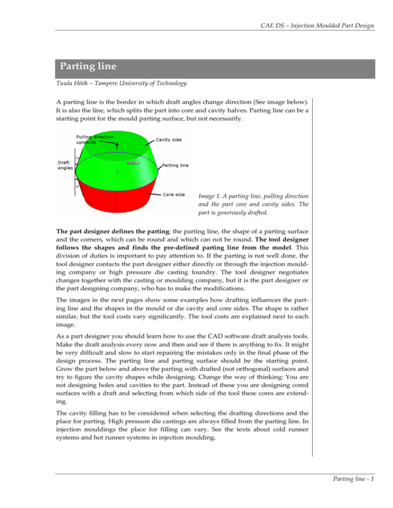
CAE DS – Injection Moulded Part Design Parting line Tuula Höök – Tampere University of Technology A parting line is the border in which draft angles change direction (See image below). It is also the line, which splits the part into core and cavity halves. Parting line can be a starting point for the mould parting surface, but not necessarily. Image 1. A parting line, pulling direction and the part core and cavity sides. The part is generously drafted. The part designer defines the parting: the parting line, the shape of a parting surface and the corners, which can be round and which can not be round. The tool designer follows the shapes and finds the pre‐defined parting line from the model. This division of duties is important to pay attention to. If the parting is not well done, the tool designer contacts the part designer either directly or through the injection mould‐ ing company or high pressure die casting foundry. The tool designer negotiates changes together with the casting or moulding company, but it is the part designer or the part designing company, who has to make the modifications. The images in the next pages show some examples how drafting influences the part‐ ing line and the shapes in the mould or die cavity and core sides. The shape is rather similar, but the tool costs vary significantly. The tool costs are explained next to each image. As a part designer you should learn how to use the CAD software draft analysis tools. Make the draft analysis every now and then and see if there is anything to fix. It might be very difficult and slow to start repairing the mistakes only in the final phase of the design process. The parting line and parting surface should be the starting point. Grow the part below and above the parting with drafted (not orthogonal) surfaces and try to figure the cavity shapes while designing. Change the way of thinking: You are not designing holes and cavities to the part. Instead of these you are designing cored surfaces with a draft and selecting from which side of the tool these cores are extend‐ ing. The cavity filling has to be considered when selecting the drafting directions and the place for parting. High pressure die castings are always filled from the parting line. In injection mouldings the place for filling can vary. See the texts about cold runner systems and hot runner systems in injection moulding. Parting line ‐ 1 CAE DS – Injection Moulded Part Design Parting examples Image 2. Parting is in the middle of the part. The core is divided to two sections: one half of the core is in the mould cavity side and the other half in the core side. Core and cavity sides are exactly similar. Both sides need die‐sink EDM production method or placing a separate fixed core. This solution is expensive. Part draft analysis results Mould/die core side Mould/die cavity side Part draft analysis results Image 3. Parting in the bottom of the part. The core is divided to two sections like in the image 2: one half of the core is in the mould cavity side and the other half in the core side. The core side is rather simple to manufacture. It has one relatively low core. The cavity side consists of a low core and a cavity for the part outer shapes. The slot between the core and the cavity in the mould/die cavity side has to be prepared by die‐sink EDM or by extracting a separate fixed core from the cavity. This solution is cheaper than in the previous example, but still not the cheapest one. Mould/die core side Mould/die cavity side Parting line ‐ 2 CAE DS – Injection Moulded Part Design Part draft analysis results Image 4. Parting in the bottom of the part. The core is located fully in the mould/die core side and the cavity on the cavity side. The cheapest and best solution from the mould/die making point of view. There is one high core placed to the mould/die core side and one deep cavity on the cavity side. Both shapes can be prepared by common machining methods. If it is necessary to save core material, it is possible to extract a separate fixed core to the core side of the tool. The part wall thickness is universal. Mould/die core side Mould/die cavity side Image 5. Parting in the bottom of the part. The core is located in the same mould/die half as the cavity. The cavity side of the tool is flat. The core side contains a deep slot. The best manufacturing method is by extracting a separate fixed core. Part draft analysis results Mould/die cavity side Mould/die core side Parting line ‐ 3 CAE DS – Injection Moulded Part Design Image 6. A separate fixed core in the tool core side. Right: A cross section image. The wall thickness is not universal in this structure. Next there are two examples of a cup shaped part with a cored hole at the bottom. The draft angle direction and the place for a parting line are obvious. The core can be placed either to the fixed or to the moving die half. The draft angle direction is set according to the selection. Image 7. A cup shaped part with a boss and a cored hole at the bottom. The core is in the fixed die/mould half. The draft angle directions are as shown in the image. The parting line follows the cup opening and the core top in the corners where the surface color changes from green to red. The die/mould moving half consists of the part inner surfaces. The fixed half consists of the cup outer surfaces and the core surfaces. This solution is rather easy to machine and cheaper than the second option. Part draft analysis results Mould/die core side Mould/die cavity side Parting line ‐ 4 CAE DS – Injection Moulded Part Design Image 8. The boss is as in the previous example, but the fixed core is in the moving die/mould half. Pay attention to the fillet between the fixed core surface and the part outer surface. The fillet has to end in a draft angle in the corner between the core and cavity surfaces (in the image that is the corner between red and green colors). One can make very easily a mistake here. Image 9. Left: Mould core side. Almost all the core surfaces are here. Also the fixed core, which forms the hole in the middle of the boss. The core has to be extracted, and machined as a sepa‐ rate piece. This solution is more expensive, because there is a need to machine a separate fixed core and wire EDM a hole for the fixed core. Right: Mould cavity side. The shape is simple and easy to manufacture. The parting surface should always be flat. It is the cheapest and most practical solu‐ tion. In order to keep the molten material inside the cavity, the mould/die parting surface has to be perfectly planar and both halved has to fit perfectly together. It is very difficult to grind a shaped surface so that both sides of the mould/die have ex‐ actly the same shape and fit together. Usually in the case of a cup‐shaped part with a non‐flat opening it is still possible to manufacture the mould/die with a flat parting surface. Also in the case of one open side. See the examples in the following images. Parting line ‐ 5 CAE DS – Injection Moulded Part Design Image 10. A cup shaped part with a non‐flat opening and the core side of the mould/die. The parting surface is flat and secures the efficient closing of the tool. Image 11. Left: Parting surface as the SolidWorks parting line tool suggests it. The shape is not nice from the machining point of view. Not a recommended solution. Right: Well designed parting surface. Pay attention to the case of round shapes ending to a parting line. It is a very common mistake to create a zero draft condition in the parting line. Aluminum high pressure die castings are especially sensitive to solder formation if there are even small zero draft surfaces in the cavity. When designing injection mouldings with textured sur‐ faces, the designer should also be especially careful with drafting. See the following image. Another similar example was in the image 8. There was a filleted corner in the border of core and cavity surfaces. Image 12. No clear parting. Avoid this condition. End the surfaces to an angle. Parting line ‐ 6
